
User's Manual
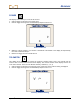
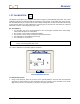
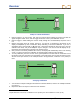
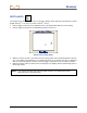
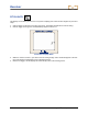
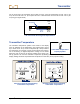
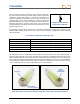
Table Of Contents
- Safety Precautions and Warnings
- Dear Customer:
- Introduction
- Receiver
- Transmitter
- Remote Display
- Battery Charger
- Locating Instructions
- Appendix A: System Specifications and Maintenance Requirements
- Appendix B: Projected Depth Versus Actual Depth and the Fore/Aft Offset
- Appendix C: Calculating Depth Based on Distance Between FLP and RLP
- LIMITED WARRANTY

Receiver
1-PT CALIBRATION
This display menu allows you to calibrate the receiver using the 1-point calibration procedure. The 1-point
calibration procedure is performed with the transmitter in the housing, as described later in this section.
DCI recommends that you verify that the receiver’s depth readings are accurate at several locations using
a tape measure before you drill. Calibration is necessary prior to first-time use and whenever a different
transmitter, receiver, or housing is going to be used.
Do not calibrate if:
You are within 10 ft (3 m) of metal structures, such as steel pipe, chain-link fence, metal siding,
construction equipment, or automobiles.
The receiver is over rebar or underground utilities.
The receiver is in the vicinity of excessive electrical interference.
The transmitter is not installed in the housing.
The transmitter is not turned on.
NOTE: Calibration is necessary prior to first-time use and whenever a different transmitter, re-
ceiver, or housing is going to be used.
The 1-point calibration menu display appears as follows:
1-Point Calibration Screen
To calibrate the receiver:
1. Using a tape measure, place the receiver on the ground parallel to and level with the transmitter
(powered on and in housing) so that the distance from the centerline of the transmitter to the inside
edge of the receiver is 10 ft (3.05 m), as shown in the figure given below.
DigiTrak
®
LT2™ Operator’s Manual 23