
User's Manual
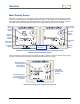
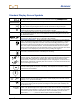
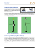
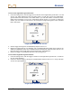
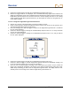
Table Of Contents
- Safety Precautions and Warnings
- Dear Customer:
- Introduction
- Receiver
- Transmitter
- Remote Display
- Battery Charger
- Locating Instructions
- Appendix A: System Specifications and Maintenance Requirements
- Appendix B: Projected Depth Versus Actual Depth and the Fore/Aft Offset
- Appendix C: Calculating Depth Based on Distance Between FLP and RLP
- LIMITED WARRANTY

Receiver
Standard Display Screen Symbols
Height-Above-Ground Icon – Appears above the ground symbol when
the height-above-ground function is on and shows the current height setting.
Ground – Represents the surface of the ground.
Locating Icon – Represents a bird’s-eye view of the receiver. This icon is referred to as
the “box” when using the target-in-the-box and line-in-the-box locating techniques.
Target – Represents the front and rear locate points (FLP and RLP). When the receiver is
positioned directly above a locate point, the target will be in the box.
Line – Represents locate line (LL). When the receiver is positioned directly above the
LL, the line will be in the box. The LL also allows for off-track locating when access over
the drill head is limited.
Transmitter Battery – Depicts the battery status of the transmitter. This case shows five
of seven bars, which means there is 71% battery life remaining.
Transmitter Temperature – Shows temperature status of transmitter. An arrow appears
next to the thermometer pointing either up to indicate increasing temperature, or down to
indicate decreasing temperature. The three curved lines extending from the top of the
thermometer appear if the transmitter has reached a dangerous temperature of 118°F or
48°C and requires immediate attention. The thermometer will flash off and on at 140°F
(60°C) to further indicate the need for immediate action to cool the transmitter. The actual
temperature can be displayed in place of the pitch by holding the trigger in.
Receiver Battery – Depicts the battery status of the receiver. This case shows five of
seven bars, which means there is 71% battery life remaining.
Transmitter Pitch – Shows the inclination of the transmitter, displayed in either percent
slope or degrees. The pitch value is shown with a drill head indicator behind it that points
up for positive pitch and down for negative pitch. When using percent slope for pitch
measurements, a value from 0 to 100 will appear; when using degrees, a value from 0 to
45 will appear, followed by a decimal point and a value of 0 or 5. Pitch measurements are
given in 0.5-degree increments.
Pitch/Roll Update Indicator - The dot in the center of the clock should blink 2 times per
second, indicating that current pitch, roll, battery, and temperature information is being
received from the transmitter.
Transmitter Roll – The clock shows the 12 roll positions of the transmitter.
Telemetry Channel Setting – Shows the current channel setting for the receiver. The
receiver must be set to the same channel as the remote display. There are four channel
settings (1, 2, 3, 4) and an Off setting.
+/–
Plus/Minus Locating Indicator – The plus or minus sign in front of the signal strength
value can be used to guide the operator in finding the locate points (FLP and RLP) and
the locate line (LL).
Signal Strength – Displays the amount of signal from the transmitter when the trigger is
held in. The signal strength scale ranges from 0 to 999, where 0 indicates no signal and
999 indicates signal saturation (receiver and transmitter are very close). When the trigger
is not held in and the receiver is saturated (too close to transmitter), you will see four
dashed lines ( — — — — ) where the distance/depth number should display.
DigiTrak
®
LT2™ Operator’s Manual 15