
User's Manual
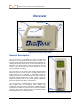
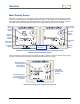
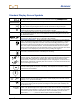
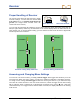
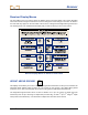
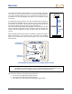
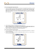
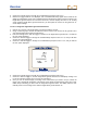
Table Of Contents
- Safety Precautions and Warnings
- Dear Customer:
- Introduction
- Receiver
- Transmitter
- Remote Display
- Battery Charger
- Locating Instructions
- Appendix A: System Specifications and Maintenance Requirements
- Appendix B: Projected Depth Versus Actual Depth and the Fore/Aft Offset
- Appendix C: Calculating Depth Based on Distance Between FLP and RLP
- LIMITED WARRANTY

Receiver
Main Display Screen
When the LT2 receiver is on, the display screen shows the standard locating mode display (see figure
below) as the default display. The display symbols that appear on the locating screen are identified in the
figure below and described in the “Standard Display Screen Symbols” table on the next page. Note that
the height-above-ground setting will only appear if the height-above-ground function is enabled.
Height-
Above-
Ground
Setting
Target-in-
the-box
®
Locating
Display
T
ransmitter
Roll (Clock)
Pitch/Roll
Upda
te
Indicator
T
ransmitter
Pitch
Distan
ce to
Transmitter
T
ransmitter
Battery
Transmitter
Temperature
Receiver
Battery
Standard Locating Mode Display with Height-Above-Ground Function
Enabled (Left) and Without (Right)
When the operator holds in the trigger, the display changes to show the telemetry channel setting, signal
strength, and transmitter temperature (see figure below and table on next page).
Telemetry Channel
Setting Replaces
Height-Above-
Ground Setting
Signal Strength (with
+/– Locating Symbol)
Replaces Distance to
Transmitter
Transmitter
Temperature
Replaces Pitch
Reading
Standard Locating Mode Display with Trigger In
14 DigiTrak
®
LT2™ Operator’s Manual