
User's Manual
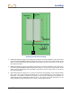
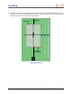
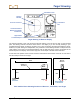
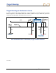
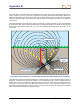
Table Of Contents
- Safety Precautions and Warnings
- Dear Customer:
- Introduction
- Receiver
- Transmitter
- Remote Display
- Battery Charger
- Locating
- The Target Steering Function
- Appendix A: System Specifications and Maintenance Requirements
- Appendix B: Projected Depth Versus Actual Depth and the Fore/Aft Offset
- Appendix C: Calculating Depth Based on Distance Between FLP and RLP
- LIMITED WARRANTY

Target Steering
76 DigiTrak
®
F2™ Operator’s Manual
Target Steering in Interference Areas
In areas of passive and/or active interference, it may be advisable to physically elevate the receiver
above the ground. In the example below, the receiver is placed 3 ft (1 m) above the ground. To
compensate, the target depth value will be set to 8’6” (2.7 m).
20
’
4
”
4
’
6
”
5
’
6
”
5
’
6
”
4
’
6
”
Transmitter
Back of
Receiver
Actual Position
of Transmitter
Target
Target
Surface of
Ground
3
’
3
’
This Height
Must Be Added
to Target Depth
Side and Back End Views of Transmitter, Target, and Raised Receiver
3-2200-00-B
Drill
Rig