
User's Manual


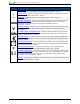


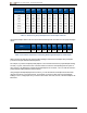
Table Of Contents
- Important Safety Instructions
- Getting Started
- Receiver
- Receiver Menus
- Locating Basics
- Advanced Locating
- Transmitter
- Appendix A: System Specifications
- Appendix B: Receiver Screen Symbols
- Appendix C: Projected Depth Versus Actual Depth and the Fore/Aft Offset
- Appendix D: Calculating Depth Based on Distance Between FLP and RLP
- Appendix E: Reference Tables

DIGITALCONTROLINCORPORATED
70 DigiTrak Falcon F5
®
Operator's Manual
1. LP (2)
2. LL
3. Fore/aft offset
4. Projected depth
5. Actual depth
6. 30% (17°) pitch
Side View of Actual Depth due to Fore/Aft Offset When Steep
andDeep
The above figure shows a transmitter positioned in a drill string that is drilling at either a positive or a negative
pitch—the pitch is positive if you are drilling left to right, negative if you are drilling right to left. The
transmitter’s signal field is also pitched at the same angle as the transmitter. The locate line (LL), which is
where the depth measurement is taken, is the horizontal component of the transmitter’s signal field flux lines.
That is, the LL is found where the flux lines are horizontal, illustrated by short horizontal yellow lines above.
The locate points (FLP and RLP) are also shown above. These points are located at the vertical components
of the signal field illustrated by short vertical yellow lines above. Note how the locate points are not the same
distance from the LL when the transmitter is pitched. Again, this situation requires compensation for the
projected depth and the fore/aft offset.
Using the following tables to find:
l actual depth based on the receiver’s depth reading (projected depth) and the transmitter pitch – TableC1
l fore/aft offset based on the receiver’s depth reading (projected depth) and the transmitter pitch –
TableC2
l projected depth that you will see on the receiver during drilling if you know the required depth (actual
depth) of your installation – TableC3
l conversion factors for determining the projected depth from the actual depth, or the actual depth from
the projected depth at various transmitter pitches – TableC4
These "steep and deep" calculations for projected depth are important when using a bore plan that has
specified target depths on steeper and deeper bores.