
User's Manual
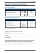
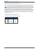
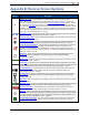
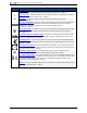

Table Of Contents
- Important Safety Instructions
- Getting Started
- Receiver
- Receiver Menus
- Locating Basics
- Advanced Locating
- Transmitter
- Appendix A: System Specifications
- Appendix B: Receiver Screen Symbols
- Appendix C: Projected Depth Versus Actual Depth and the Fore/Aft Offset
- Appendix D: Calculating Depth Based on Distance Between FLP and RLP
- Appendix E: Reference Tables

DIGITALCONTROLINCORPORATED
68 DigiTrak Falcon F5
®
Operator's Manual
Symbol Description
Receiver Icon – Indicates the position of the receiver relative to the ground for the HAG function,
depth readings, in-ground calibration, and the Target Steering function. Page37
R
Reference Lock – Indicates a reference signal has been obtained for displaying the locate line.
Displays at the top of the Locate screen. Page46
RO
Roll Offset – Indicates roll offset is enabled. Displays at the bottom left of the roll
indicator. Page22
Roll/Pitch Update Meter – Shows the quality of data reception from the transmitter (specifically,
data rate). A full bar is the best signal. A shorter bar indicates the receiver is in an area of
interference or you are reaching the range limit of the transmitter, relative to
interference. Page36
Telemetry Channel – The channel used to communicate with the remote display on the drill rig.
Select whichever channel offers the best performance. Select channel 0 to turn telemetry
off. Page21
Transmitter Battery Strength/Drill Head – Depicts the remaining battery life of the transmitter
when alkaline batteries are used. Also represents the position of the drill head relative to the
receiver in the Depth screen. Page37
Transmitter Pitch – The number next to this icon on the Locate screen is the transmitter pitch
angle. It is also the Settings menu icon for changing the pitch angle units between percent and
degrees. Page36
Transmitter Roll Indicator – Shows the transmitter’s roll position. The roll value appears in the
center of the clock. When roll offset is enabled, the letters “RO” appear at the bottom left and the
indicator becomes a circle. Page36
Transmitter Signal Strength – The number next to this icon on the Locate screen is the
transmitter signal strength. Maximum signal strength is about 1200. Page36
or
Transmitter Temperature – The number next to this icon shows the transmitter temperature. An
up or down arrow indicates the trend from the last reading. The icon will display steam and flash
when the transmitter becomes dangerously hot, indicating the transmitter must be cooled
immediately or it will be damaged. Page61
Warning – This error symbol indicates a failure in a self-test or a need to calibrate the receiver to
one or both transmitter bands. Page36