
User's Manual
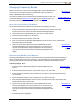
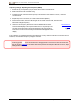
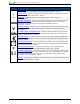
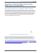

Table Of Contents
- Important Safety Instructions
- Getting Started
- Receiver
- Receiver Menus
- Locating Basics
- Advanced Locating
- Transmitter
- Appendix A: System Specifications
- Appendix B: Receiver Screen Symbols
- Appendix C: Projected Depth Versus Actual Depth and the Fore/Aft Offset
- Appendix D: Calculating Depth Based on Distance Between FLP and RLP
- Appendix E: Reference Tables

DIGITALCONTROLINCORPORATED
DigiTrak Falcon F5
®
Operator's Manual 67
AppendixB: Receiver Screen Symbols
Symbol Description
A
Attenuated Signal – Indicates signal attenuation is in effect due to the presence of excessive
interference, or when locating within 1 m of the transmitter. The receiver automatically
attenuates the transmitter signal when locating at shallow depths to reduce excessive signal
strength. The A displays at the bottom left of the frequency optimizer results (page 25) , or at the
top right of the roll indicator (page 36) on the locate screen, or beneath the Calibration Failure
icon. Attenuation while locating in close proximity to the transmitter is normal; attenuation during
calibration or frequency optimization is a warning to relocate to a location with less interference.
The receiver will not calibrate when the A icon and signal strength are flashing red, indicating
the presence of extreme interference. Page14
Band Up or Down – Indicates whether the receiver is currently using the Up or Down optimized
band. Located in the title bar of the Locate screen. Page13
Calibration Signal High – Displays after a failed calibration, often because the transmitter is too
close to the receiver. Page16
Calibration Signal Low – Displays after a failed calibration, often because the transmitter is not
powered on or is on a different (Up or Down) frequency band than the receiver. Page16
Calibration Attenuation Error – Displays after a failed calibration. If attenuation is in effect due
to only moderate interference, the system will still calibrate; however, it is best practice to
relocate to a quieter location where attenuation is not required. If the signal strength and A
attenuation icon on the locate screen are flashing red, this indicates extreme interference, and a
calibration will fail. Page15
Globe Icon – Shown on the receiver startup screen, the number inside (shown blank here)
identifies the regional designation, which must match that on the transmitter battery
compartment. Page6
Ground Level – Represents the ground for the HAG function, depth readings, and the in-ground
calibration procedure. Page37
Locate Line – The locate line (LL) always displays perpendicular to the transmitter. The locate
line (LL) is found between the front and rear locate points only after a reference lock (see below)
has been obtained. May also include the transmitter yaw angle in degrees. Page37
,
Locating Ball/Target – Represents the front and rear locate points (FLP and RLP). When the
locate line appears, the locating ball will become a solid circle (ball) representing the
approximate locate point. Page36
Locating Icon (the receiver) – Represents a bird’s-eye view of the receiver. The square at the
top of this icon is referred to as the “box” in the terms Ball-in-the-Box™ and Line-in-the-Box
locating. Page36
Max mode – Max mode begins when the trigger is held longer that five seconds during a depth
reading. Page37
Max Mode Timer – Provides a visual indication that Max mode is active (trigger held). Replaces
the roll/pitch update meter. It will remain red if no stable signal can be found. Page37
Pitch Assumed Zero – Indicates that since no pitch data is currently available, the pitch is
assumed to be zero for depth, predicted depth, and AGR calculations. Page37
Pressure – When using a fluid pressure transmitter, the number next to this icon on the Locate
screen indicates the pressure reading. If the pressure reaches an over-limit condition (from 689–
1724 kPa), the value will appear red. When the pressure reaches the overload condition (over
1724 kPa), the value will display as “+OL”. Page23
Receiver Battery Strength – Shows the remaining battery life of the receiver. Appears above
the main menu. When battery life is low, the icon will flash on the Locate screen. Page13