
User's Manual
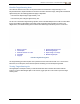
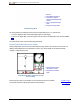
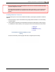


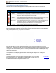
Table Of Contents
- Important Safety Instructions
- Getting Started
- Receiver
- Receiver Menus
- Locating Basics
- Advanced Locating
- Transmitter
- Appendix A: System Specifications
- Appendix B: Receiver Screen Symbols
- Appendix C: Projected Depth Versus Actual Depth and the Fore/Aft Offset
- Appendix D: Calculating Depth Based on Distance Between FLP and RLP
- Appendix E: Reference Tables

DIGITALCONTROLINCORPORATED
DigiTrak Falcon F5
®
Operator's Manual 61
Transmitter Drill Head Requirements
For maximum transmitter range and battery life, the slots in the drill head must meet minimum length and
width requirements and be correctly positioned. DCI's transmitters require three slots equally spaced around
the circumference of the drill head for optimal signal emission and maximum battery life. Measure slot
lengths on the inside of the drill head; slots must be at least 1.6mm (1/16 in.) wide. DCI transmitters fit
standard housings but may require a battery cap adapter in some cases.
1. Battery cap
2. Slot position
3. Front end cap
A. Slot length
B. Distance
C. Transmitter length
A Minimum B Maximum* C
Falcon F5 Wideband 22.9 cm* 2.5 cm 38.1 cm
Falcon F5 19 in. Wideband 33.0 cm* 2.5 cm 48.3 cm
* Ideal measurement. The DCI standard slot length of 21.6 cm (A) and distance of 5.1 cm (B) remain acceptable.
A transmitter must fit snugly in its drill head. It may be necessary to wrap the transmitter with tape or O-rings
and/or use a drill head adapter for larger drill heads. Contact DCI Customer Service for more information.
The index slot in the front end cap of the transmitter should fit onto the anti-roll pin
(key) in the drill head for proper alignment. Use roll offset if the transmitter’s 12:00
position does not match that of the drill head.
Roll Offset Menu
Page 22
Use only the battery cap that accompanied the Falcon transmitter; other battery caps may look similar but
crush the batteries or make the transmitter too long to fit in a standard housing.
Temperature Status and Overheat Indicator
All DigiTrak transmitters are equipped with an internal digital thermometer. The temperature displays on the
bottom right of the receiver and remote display screens next to the transmitter temperature symbol .
Normal drilling temperatures range from 16 to 40°C. Suspend drilling when temperatures exceed 36°C to
permit cooling.
A small triangle beside the temperature icon indicates whether the temperature is trending up or down
since the last reading.
Because the digital thermometer is inside the transmitter, temperature increases due to
external drilling conditions will take time to transfer to the transmitter. Resolve increases in
temperature quickly to avoid irreversible damage.
If the temperature reaches 48°C, the thermometer icon will change to show that the transmitter is becoming
dangerously hot . The transmitter must be allowed to cool immediately or it will be damaged.
To cool the transmitter, stop drilling and retract the drill one meter and/or add more drilling fluid.