
User's Manual
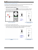
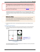
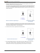
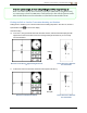
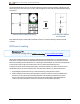
Table Of Contents
- Important Safety Instructions
- Getting Started
- Receiver
- Receiver Menus
- Locating Basics
- Advanced Locating
- Transmitter
- Appendix A: System Specifications
- Appendix B: Receiver Screen Symbols
- Appendix C: Projected Depth Versus Actual Depth and the Fore/Aft Offset
- Appendix D: Calculating Depth Based on Distance Between FLP and RLP
- Appendix E: Reference Tables

DIGITALCONTROLINCORPORATED
44 DigiTrak Falcon F5
®
Operator's Manual
The line marked LL in the bird’s-eye view image suggests the receiver will display a locate line any time it is
positioned on this plane. To prevent inaccurate locates and potentially dangerous conditions, it is imperative
to first find the front and rear locate points. Do not rely on the peak signal along the locate line.
Whenever the transmitter is pitched, the position of the locate line will be somewhat slightly
ahead of or behind the transmitter’s actual position. This slight fore/aft offset will increase with
depth (see AppendixC: Projected Depth Versus Actual Depth and the Fore/Aft Offset). In
these cases, the depth displayed on the receiver is referred to as the projected depth.
Effects of Depth, Pitch, and Topography on Distance Between FLP and RLP
The deeper the transmitter is, the farther apart the FLP and RLP will be. The distance between the FLP and
RLP with respect to the location of the LL is also affected by transmitter pitch and the topography.
When the transmitter pitch is negative, the FLP will be farther from the LL than the RLP. When the pitch is
positive, the RLP will be further from the LL than the FLP. If the ground surface or topography slopes
significantly, the locations of the FLP and RLP will also be affected with respect to the LL even if the
transmitter itself is level.
1. Bird's-eye view
(looking down)
2. RLP (2)
3. LL (2)
4. Transmitter (2)
5. FLP (2)
6. Drill rig
7. Bore path
8. Side view
9. Surface of ground
Effect of Pitch on Distance Between FLP, RLP, and LL
For a detailed explanation of how to track the transmitter when it is steep and deep, see AppendixC on
page69.
To calculate depth (for comparison to the receiver’s depth reading) using the distance between the locate
points and the pitch of the transmitter, see AppendixD: Calculating Depth Based on Distance Between FLP
and RLP on page 73.