
User's Manual
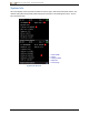
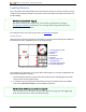
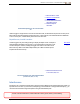
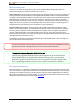
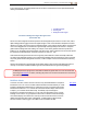
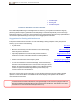
Table Of Contents
- Important Safety Instructions
- Getting Started
- Receiver
- Receiver Menus
- Locating Basics
- Advanced Locating
- Transmitter
- Appendix A: System Specifications
- Appendix B: Receiver Screen Symbols
- Appendix C: Projected Depth Versus Actual Depth and the Fore/Aft Offset
- Appendix D: Calculating Depth Based on Distance Between FLP and RLP
- Appendix E: Reference Tables

DIGITALCONTROLINCORPORATED
DigiTrak Falcon F5
®
Operator's Manual 41
In the following figure, the red flag area denotes an increase in noise detected on the optimized band while
walking the intended bore path.
1. Intended bore path
2. Red flag area
3. Background noise signal
One-Person Background Signal Strength Check
(Transmitter Off)
Return to the area of highest interference (between the red flags above) and from the Locate screen, take a
depth reading (hold the trigger) and note the signal strength. Power on the transmitter and place it the same
distance to the side of the receiver as the intended bore depth. Verify that the roll/pitch data is consistent and
correct in the flagged area. The transmitter’s signal strength should generally be a minimum of 150 points
greater than the background noise reading. For example, if this area of greatest interference produced a
reading of 175, the reading with the transmitter on at this location, and at a distance from the receiver equal to
the maximum intended bore depth, should be a minimum of 325 (175 + 150).
Areas where the background noise level is too high may make it difficult to obtain roll and pitch data and
accurate locates and depth readings. If the signal strength readings with the transmitter on were not at least
150 points greater than the background noise level, conduct a roll/pitch check as described in the following
section.
Note that the transmitter’s signal strength will be slightly higher in this test than while drilling because it is
currently not encased in the drill head below ground, which will diminish the signal strength slightly.
An A displayed at the top right of the roll indicator at distances greater than 2.5 m from the transmitter
means signal attenuation is in effect, indicating the presence of excessive interference that can lead to
inaccurate depth readings.
Roll/Pitch Check
At the exit of the bore, turn the receiver to face the entry and install batteries in the paired
transmitter to turn it on. Have a coworker hold the transmitter and stand beside you. Walk
together in parallel back toward the entry, keeping the receiver over the bore path and the
transmitter at a distance of 1 to 1.5 times the current intended bore depth; where the bore
is deeper, your coworker will be farther away. Periodically stop and change the
transmitter’s roll and pitch orientation so you can verify the speed and accuracy of these
readings on the receiver. It is good practice to also have a coworker monitor the readings
at the remote display at the same time. Note any locations where the receiver or remote
display information becomes erratic or disappears. If roll/pitch data or signal strength
become unstable, hold the trigger to see if Max mode can stabilize the data.
Max Mode
Page 37