
User's Manual
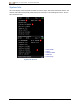
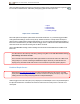
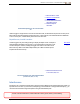
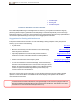
Table Of Contents
- Important Safety Instructions
- Getting Started
- Receiver
- Receiver Menus
- Locating Basics
- Advanced Locating
- Transmitter
- Appendix A: System Specifications
- Appendix B: Receiver Screen Symbols
- Appendix C: Projected Depth Versus Actual Depth and the Fore/Aft Offset
- Appendix D: Calculating Depth Based on Distance Between FLP and RLP
- Appendix E: Reference Tables

DIGITALCONTROLINCORPORATED
DigiTrak Falcon F5
®
Operator's Manual 37
The roll/pitch update meter displays the quality of roll/pitch data being received from
the transmitter. When the meter is empty, no roll/pitch data is being received, and
none will appear on either the receiver or the remote display. Depth and predicted
depth readings may still be taken, but the receiver will assume the transmitter has a
pitch of zero, as indicated by the image to the right appearing on the Depth or
Predicted Depth screen.
Pitch Assumed
Zero
Locate Screen Shortcuts
The following shortcuts are available from the Locate screen.
Task Operation Page
DataLog (if enabled) Hold trigger, toggle right 29
Depth Screen Hold trigger at locate line (LL) 37
Flag or Pin during DataLog Toggle right 31
Max Mode Hold trigger at least five seconds 37
Main Menu Toggle down 13
Predicted Depth Screen Hold trigger at front locate point (FLP) 38
Target Steering Toggle up 54
Band Selection Menu Hold toggle right 28
Depth Screen
Hold the trigger with the receiver at the locate line (LL) to display the
Depth screen.
Locate Points (FLP & RLP) and
Locate Line (LL)
Page 43
1. Locate point (front or rear)
2. Bird's-eye view
3. Locate line (LL)
4. Height-Above-Ground (HAG)
setting on
5. Ground level
6. Transmitter depth
7. Tx battery strength
Depth Screen at LL with HAG On
When the HAG setting is disabled, the receiver will be shown on the ground and
must be placed on the ground during depth readings.
Height-Above-
Ground (HAG)
Page 18
Max Mode Noise Filtering
The purpose of Max mode noise filtering is to stabilize erratic roll/pitch data, depths, and locates when drilling
at the very limit of the ability of the transmitter due to extreme depth or interference, which will vary by
jobsite.