
User's Manual

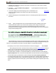
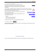
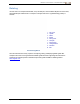
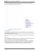
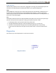
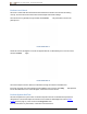
Table Of Contents
- Important Safety Instructions
- Getting Started
- Receiver
- Receiver Menus
- Locating Basics
- Advanced Locating
- Transmitter
- Appendix A: System Specifications
- Appendix B: Receiver Screen Symbols
- Appendix C: Projected Depth Versus Actual Depth and the Fore/Aft Offset
- Appendix D: Calculating Depth Based on Distance Between FLP and RLP
- Appendix E: Reference Tables

DIGITALCONTROLINCORPORATED
DigiTrak Falcon F5
®
Operator's Manual 25
1. Maximum noise reading
2. Current Up band
3. Current Down band
4. Current optimized noise
readings
5. Median kHz of each band
6. Band selector
7. Pair
8. Exit
Frequency Optimizer Results
4. To measure noise readings from the entire intended bore, simply walk the bore with the frequency
optimizer results displayed, keeping the receiver parallel to the bore path. As the receiver continues
sampling background noise, it marks the maximum noise reading of each band at the top of each
bar.
Optimize as often as you want. You can't wear it out.
If noise levels rise substantially at any point along the bore, consider selecting and pairing
one band (see next step) that performed well up to this point. Then select Exit and restart
FO at this point to perform a new scan and select and pair a second band for use in this
higher-interference area. Optimize as often as you want and wherever you want before
assigning a band.
5. Toggle to the band you want to use and click to select. Typically this will be a band with a low
interference level that did not experience high maximum noise readings along the bore path.
Band Number 7 11 16 20 25 29 34 38 43
Range in kHz 4.5 – 9.0 9.0 – 13.5 13.5 – 18 18 – 22.5 22.5 – 27 27 – 31.5 31.5 – 36 36 – 40.5 40.5 – 45
6. Select whether to assign this as the Up or Down band (the band the Tx powers on with when facing
Up or Down).
Up Down
If the band number you want to use is already displayed at the right edge of the screen and
marked in red on the bottom of the graph, select it anyway. The band you select now will be
optimized with different frequencies than the last time that band was used.