
User's Manual

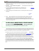
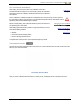
Table Of Contents
- Important Safety Instructions
- Getting Started
- Receiver
- Receiver Menus
- Locating Basics
- Advanced Locating
- Transmitter
- Appendix A: System Specifications
- Appendix B: Receiver Screen Symbols
- Appendix C: Projected Depth Versus Actual Depth and the Fore/Aft Offset
- Appendix D: Calculating Depth Based on Distance Between FLP and RLP
- Appendix E: Reference Tables

DIGITALCONTROLINCORPORATED
24 DigiTrak Falcon F5
®
Operator's Manual
Frequency Optimization and Transmitter Selection
This section addresses Falcon technology's ground-breaking frequency optimizer (FO) feature, which finds
the lowest-noise (optimal) group of frequencies available in each of nine bands. When the results display in
graph form showing the levels of active interference in each band, choose the one or two bands you want to
use, pair, and you're ready to calibrate and start drilling.
You can switch the transmitter between the two optimized bands at any time, either pre-bore or mid-bore.
Start in the optimized band that works best for the normal-interference portion of the bore and switch to the
other band that works better for the portion that has higher interference. Or use one optimized band for the
whole bore, or start drilling in one optimized band and switch only if you need to. The choice is yours.
Do I have to optimize every time I power the receiver on?
Page59
No, the receiver remembers both optimized bands until you pair it to a new band. Power
the transmitter on horizontally to use the last active band. But don't forget to optimize at
your next bore.
If my optimized band worked great at my last jobsite, can I keep using it at my next one?
Because sources of interference differ at every jobsite, DCI recommends optimizing at
every jobsite to obtain the best selection of frequencies for the current conditions.
Frequency Optimization
To optimize and select a frequency band:
1. Ensure all transmitters are powered off or are more than 30 m away from the receiver.
2. Take your receiver to the point along the proposed bore that you expect to have the greatest amount
of noise (active interference).
3.
With the receiver parallel to the bore path,open the Main menu, select Transmitter Selection ,
then Frequency Optimization (FO) .
When frequency optimization is complete, the receiver shows active noise readings in each of the nine
frequency bands using an optimized selection of the lowest-noise frequencies within each band. The
shorter the bar on the graph, the less interference present in that band.
-90 to -72 dB Low interference levels
-72 to -54 dB Moderate interference
-54 to -18 dB Interference will become an issue as depth increases