
User's Manual


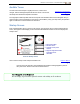
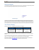
Table Of Contents
- Important Safety Instructions
- Getting Started
- Receiver
- Receiver Menus
- Locating Basics
- Advanced Locating
- Transmitter
- Appendix A: System Specifications
- Appendix B: Receiver Screen Symbols
- Appendix C: Projected Depth Versus Actual Depth and the Fore/Aft Offset
- Appendix D: Calculating Depth Based on Distance Between FLP and RLP
- Appendix E: Reference Tables

DIGITALCONTROLINCORPORATED
8 DigiTrak Falcon F5
®
Operator's Manual
2. Power on the receiver and from the Main menu select
Transmitter Selection, then Frequency Optimizer
(FO) .
,
Frequency Optimizer
Page 24
3. With the FO results active, walk the entire intended bore path with the receiver and note areas of
high background noise (active interference). The higher a frequency band's bar is on the graph, the
greater the interference. Note which band remains consistently low, since the band with the lowest
level of interference will likely be the one you want to use.
Assign Frequency Bands
1. On the receiver, click to move the selector on the bottom of the frequency optimizer graph to the
band you want to use and hold briefly to select.
2. Assign as the Up or Down band.
3. Optional: select and assign a second frequency band.
4.
Select Pair .
5. Insert batteries in the transmitter, positive end first, install the battery cap, and allow several
seconds for the transmitter to fully power on and begin sending data to the receiver.
6.
Align the receiver and transmitter IR windows within four cm of each other. Select to open the
pairing menu, then again to pair.
Are high frequency bands better than low frequency bands?
Interference varies with time and location, and no band works perfectly in all conditions.
Different bands are better for different kinds of interference. Lower frequency bands like
7 and 11 are typically better around rebar, passive interference, and salt water. The middle
frequency bands have slightly stronger signal strengths that can perform better in deeper
bores, plus have longer Target Steering capability. The highest bands have slightly less
signal strength but tend to perform better around active interference such as power lines.
Interference Check
Now that your transmitter is paired with your receiver, walk the bore with
both the receiver and transmitter powered on to check for active
interference on both frequency bands.
Interference
Page 39
Changing Frequency Bands
Page 63
Calibrate
Perform a separate 1-point (1PT) calibration for each newly optimized frequency
band in a low-noise area with the transmitter in a housing. Always calibrate after
assigning a new frequency band.
Calibration
Page 14
If you paired two bands and want to be able to switch between them later, calibrate both bands.