
User's Manual
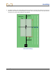

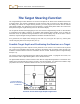
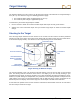
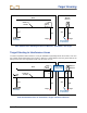

Table Of Contents
- Safety Precautions and Warnings
- Dear Customer:
- Introduction
- Receiver
- Transmitter
- Remote Display
- Battery Charger
- Locating
- The Target Steering Function
- Appendix A: System Specifications and Maintenance Requirements
- Appendix B: Projected Depth Versus Actual Depth and the Fore/Aft Offset
- Appendix C: Calculating Depth Based on Distance Between FLP and RLP
- LIMITED WARRANTY

Target Steering
DigiTrak
®
F2™ Operator’s Manual 77
20
’
4
”
4
’
6
”
5
’
6
”
5
’
6
”
4
’
6
”
Transmitter
Back of
Receiver
Actual Position
of Transmitter
Target
Target
Surface of
Ground
Side and End Views Showing Positions of Receiver, Transmitter, and Target
Target Steering in Interference Areas
To achieve separation from interference, it may be advisable to physically elevate the receiver, such as in
the example shown below where the receiver is placed at a height different than the ground level of the
drill rig. In this case, the target depth needs to be set to 8’6” (2.7 m).
20
’
4
”
4
’
6
”
5
’
6
”
5
’
6
”
4
’
6
”
Transmitter
Back of
Receiver
Actual Position
of Transmitter
Target
Target
Surface of
Ground
3
’
3
’
This Height
Must Be Added
to Target Depth
Side and Back End Views of Transmitter, Target, and Raised Receiver
Drill
Rig