
User's Manual
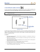
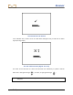
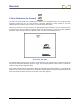
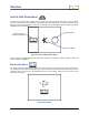
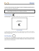
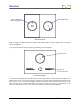
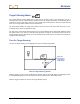
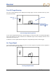
Table Of Contents
- Safety Precautions and Warnings
- Dear Customer:
- Introduction
- Receiver
- Transmitter
- Remote Display
- Battery Charger
- Locating
- The Target Steering Function
- Appendix A: System Specifications and Maintenance Requirements
- Appendix B: Projected Depth Versus Actual Depth and the Fore/Aft Offset
- Appendix C: Calculating Depth Based on Distance Between FLP and RLP
- Appendix D: Reference Tables
- LIMITED WARRANTY

Receiver
28 DigiTrak
®
F2
®
Operator’s Manual
Roll Offset Menu
Click the trigger to toggle between the activate and disable options. Hold the trigger when the desired
option is highlighted.
If you select the activate roll offset option, the following screen will appear.
Activate Roll Offset
You must then physically rotate the drill head to its 12 o’clock position, as indicated by the images at the
bottom of the screen. Then click the trigger to activate the roll offset and automatically be returned to the
locate screen. If you do not click the trigger within 8 seconds, you will be returned to the locate screen
with no change to the roll offset. Roll offset is denoted by a hollow dot in place of the solid dot on the
clock face and the letters “RO” next to the clock on both the receiver and remote displays.
Activate Roll Offset
(Shown Highlighted)
Disable Roll Offset
Transmitter Roll
Drill Head at
12 o'clock Position