
User's Manual
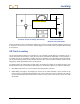
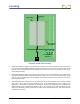
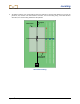

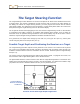
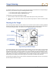
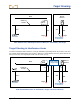

Table Of Contents
- Safety Precautions and Warnings
- Dear Customer:
- Introduction
- Receiver
- Transmitter
- Remote Display
- Battery Charger
- Locating
- The Target Steering Function
- Appendix A: System Specifications and Maintenance Requirements
- Appendix B: Projected Depth Versus Actual Depth and the Fore/Aft Offset
- Appendix C: Calculating Depth Based on Distance Between FLP and RLP
- LIMITED WARRANTY

Target Steering
76 DigiTrak
®
F2™ Operator’s Manual
The maximum distance that the receiver can be placed out ahead of the drill head for Target Steering is
35 ft (10.7 m). Over this 35-ft range, the following parameters apply:
The maximum depth change is approximately 4 ft (1.2 m).
The maximum pitch change is approximately 14%.
To determine if your desired target depth is feasible:
1. Use the receiver to obtain the current transmitter depth with respect to level ground surface.
2. Subtract the current transmitter depth from your desired target depth to obtain the desired depth
change.
Steering to the Target
Once the target depth number has been entered on the receiver and the receiver has been positioned
ahead of the tool as the target, then select remote mode from the remote's main menu (see "Main Menu"
in the Remote Display section). You will then see the Target Steering screen shown below.
Target Steering on Remote Display
The steering indicator in this case shows that the drill head is to the left and too high for the intended
path. The steering indicator should be dead center in the display if you are correctly heading to your
programmed target depth. A steering command of 4 o’clock would bring the drill head toward the target.
Note that, for quick viewing and interpretation, the pointed end of the steering indicator corresponds to the
clock position of the head. The horizontal distance from the drill head to the receiver is indicated at the
bottom left part of the display. At the bottom right, the current depth of the drill head is indicated.
A side view of the position of the receiver and of the transmitter is shown below on the left. An end view of
the same setup is shown on the right.
Horizontal Distance
Between Transmitter
and Receiver
Approximate
Transmitter Depth
Transmitter’s
Roll
Transmitter’s Pitch
Steering
Indicator
Center of Crosshairs