
User's Manual


DIGITAL CONTROL INCORPORATED
38 DigiTrak F5 Operator’s Manual
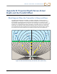
Due to the shape of the transmitter’s signal field, when it is at a pitch greater than ±30%
(±17°) and/or a depth of 15 ft (4.6 m) or more, the position of the locate line will be some
distance ahead of or behind the transmitter’s actual position. In this case, the depth displayed
on the receiver becomes what is called the projected depth. The transmitter’s distance ahead
of or behind the locate line is called the fore/aft offset.
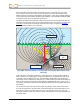
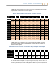
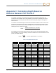
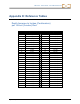
The projected depth and fore/aft offset, shown in Figure B2, must be accounted for when the
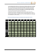
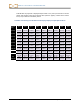
transmitter is steep and/or deep. See the tables provided later in this appendix (Table B1 and
Table B2) to determine the actual depth and fore/aft offset when you know the displayed
(projected) depth and pitch of the transmitter.
Figure B2. Projected Depth vs. Actual Depth and Fore/Aft Offset When Steep
and Deep
Figure B2 shows a transmitter positioned in a drill string that is meant to illustrate drilling at
either a positive or a negative pitch—the pitch is positive if you are drilling left to right, and it
is negative if you are drilling right to left. The transmitter’s signal field is also pitched at the
same angle as the transmitter. The locate line (LL), which is where the depth measurement is
taken, is the horizontal component of the transmitter’s signal field flux lines. That is, the LL is
found where the flux lines are horizontal, as illustrated with short horizontal yellow lines in the
figure above.
The locate points (FLP and RLP) are also shown in Figure B2. These points are located at
the vertical components of the signal field, as illustrated with short vertical yellow lines in the
figure above. Note that the locate points are not the same distance from the LL when the
transmitter is pitched. Again, this situation requires compensation for the projected depth and
the fore/aft offset.
LL
LP
LP
Fore/aft offset
30% (17°)
pitch
Projected depth
Actual depth