
User's Manual


DIGITAL CONTROL INCORPORATED
DigiTrak F5 Operator’s Manual 33
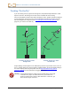
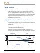
The following image shows the side view of the position of the receiver and the transmitter on
the left and an end view of the same setup on the right.
Side and End Views Showing Positions of Receiver, Transmitter, and Target
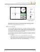
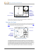
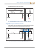
Target Steering in Interference Areas
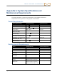
In areas of passive and/or active interference, it may be advisable to physically elevate the
receiver above the ground. In the example below, the receiver is placed 3 ft (or 1 m) above
the ground. To compensate, the target depth value will be set to 8.5 ft. (2.6 m).
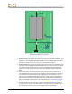
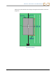
Side and Back End Views of Transmitter, Target, and Raised Receiver
20 4
4 6
5 6
5 6
4 6
20 4
4 6
5 6
5 6
4 6
3
3
Drill
rig
Surface of
ground
Back of
receiver
Target
Transmitter
Target
Actual position of
transmitter
B
a
c
k
o
f
r
e
c
e
i
v
e
r
This height
must be added
to target depth
Surface of
ground
Back of
receiver
Target
Transmitter
Target
Actual position of
transmitter