
User's Manual

DIGITAL CONTROL INCORPORATED
4 DigiTrak F5 Operator’s Manual
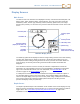
5. From the main menu, select the Settings menu to set the depth units, pitch
units, and telemetry channel. Ensure you use the same settings here as you
are on the receiver. You should also use the same system of units (English or
metric) on both devices.
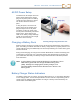
Transmitter
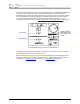
1. Compare the regional designation number on the transmitter with the number
on the receiver’s serial number label. If they don’t match, contact DCI Customer
Service.
2. Install batteries to power it on in the correct frequency (see Installing Batteries /
Power On on page xxxv).
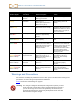
3. Using the transmitter selection menu, set the receiver to detect the type
and frequency of the transmitter (Transmitter Selection on page xxxix).
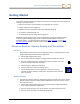
Conduct Interference Check
What Interference Is and How to Check for It
Before drilling (preferably before bidding on a project), evaluate the interference potential at
the job site. Interference can reduce the transmitter’s range or cause variable readings and
possibly result in job slowdowns. Interference is classified as either active and passive.
Active interference, also known as electrical interference or background noise, can have
varying effects upon the F5 locating equipment. Most electrical devices emit signals that can
affect your ability to locate the transmitter accurately or get good pitch/roll readings. Some
examples of active interference are traffic signal loops, buried dog fences, cathodic
protection, radio communications, microwave towers, cable TV, fiber-trace lines, utility data
transmissions, security systems, power lines, and phone lines. You can conduct a test for the
presence of active interference with the F5receiver; see the following section.
Passive interference can reduce the amount of signal received from the transmitter, which
results in deeper-than-expected depth readings or a completely blocked signal. Examples of
passive interference include metal objects such as pipes, rebar, trench plate, chain-link
fence, and vehicles. Two other examples of passive interference are saltwater/salt domes
and conductive earth, such as iron ore. You cannot conduct a test for the presence of passive
interference with your F5 system. Conducting a thorough site investigation prior to drilling is
the best method of identifying passive interference sources.
To familiarize yourself with the interference potential along your intended bore path, first
conduct a background noise check, then verify the speed and accuracy of the roll and pitch
information.
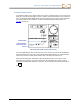
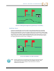
Background Noise Check
With the transmitter off, walk the bore path with the receiver while monitoring the signal
strength on the screen, noting any locations where it changes. The background noise should
generally be at least 150 points less than the transmitter’s signal strength when measured at
the maximum depth for that bore. In the following figure, the red flag area denotes an
increase in background noise.