
User's Manual

DIGITAL CONTROL INCORPORATED
DigiTrak F5 Operator’s Manual xxxiii
Transmitters
A transmitter fits inside the drill housing and generates a magnetic field that the F5 receiver
detects. The F5 receiver must be set to match the frequency of the transmitter. The receiver
must also be calibrated to the transmitter before drilling and the calibration must be verified
(see on page 3).
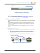
The transmitter and receiver must have matching regional designation numbers to
communicate with each other and comply with local operating requirements. The transmitter’s
regional designation number is located inside the globe icon ( ) near the serial number on
long-range and extended long-range transmitters and on the front end cap of short-range
transmitters.
Types of F5 Transmitters
DCI manufactures several different transmitters in five frequency options: 1.3 kHz, 8.4 kHz,
12 kHz, 18.5 kHz, and 19.2 kHz. F Series and F5 transmitters provide pitch readings in 0.1%
or 0.1° increments (from 0% to 100% or 0° to 45°). F5 transmitters display roll in 24 clock
positions and F Series transmitters display roll in 12 clock positions.
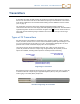
Long-range F5 and F Series transmitters measure 15 in. (38.1 cm) long and 1.25 in.
(3.175 cm) in diameter and have a depth range of approximately 65 ft (19.8 m). Several
options are available, including dual frequencies and fluid pressure monitoring.
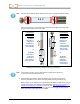
Long-Range F5 Transmitter
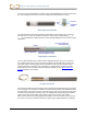
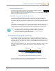
Extended long-range transmitters all measure 19 in. (48.26 cm) long and 1.25 in. (3.175 cm)
in diameter and have a depth range of approximately 85 ft (25.9 m). They are available in
12 kHz (gray) or 19.2 kHz (black) frequencies.
Extended Long-Range F5 Transmitter
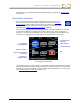
Transmitter serial
number
Regional designation number
(must match that of receiver)
Battery compartment
Front end cap with temp
dot and index slot