
User's Manual

DIGITAL CONTROL INCORPORATED
DigiTrak F5 Operator’s Manual xxxi
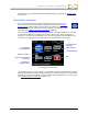
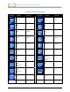
Standard Receiver Screen Symbols
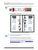
Transmitter Roll – Shows the transmitter’s roll position. A line points to the roll position, and
the roll value appears in the center of the clock. The number of roll positions is a function of
the transmitter (12 or 24). When roll offset is used, the letters “RO” appear at the bottom left.
Warning – Appears when there has been a failure in the self-test.
Globe Icon – Identifies the regional designation number that appears on the receiver
startup screen; must match the region number on the transmitter battery compartment.
Roll/Pitch Update Meter – Shows the quality of data reception from the transmitter
(specifically, data rate). This feature lets you know if you are in an area of interference or are
reaching the range limit of the transmitter.
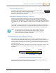
Transmitter Pitch Angle – The number next to this icon on the Locate Mode screen
indicates the transmitter pitch. It is also the menu selection icon for changing the pitch angle
units between percent and degrees.
Transmitter Signal Strength – The number next to this icon on the Locate Mode screen
indicates the transmitter signal strength.
or
Transmitter Temperature – The number next to either of these icons shows the
temperature of the transmitter. An up or down arrow will accompany a change in
temperature. The icon on the right represents dangerous drilling temperatures.
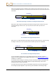
Receiver Icon – Indicates the position of the receiver relative to the ground for the height-
above-ground (HAG) function, depth readings, the two-point calibration procedure, and the
Target Steering function.
Ground Level – Represents the ground for the HAG function, depth readings, and the two-
point calibration procedure.
Locating Icon – Represents a bird’s-eye view of the receiver. The square at the top of this
icon is referred to as the “box” in the terms target-in-the-box and line-in-the-box locating.
Locate Target – Represents the front and rear locate points (FLP and RLP). See Locating
on page 15.
Locate Line – Represents the locate line (LL), which is perpendicular to the transmitter. The
LL is found at some location between the front and rear locate points only after a reference
point has been obtained. See Locating on page 15.
R
Reference Lock – Indicates that a reference signal has been obtained for locating the
transmitter. See Locating on page 15.
Transmitter Battery/Drill Head – Depicts the remaining battery life of the transmitter when
alkaline batteries are used (full battery shown here). Also used to represent the position of
the drill head relative to the receiver in the depth screen.