F5 ® Directional Drilling Locating System Operator’s Manual DIGITAL CONTROL INCORPORATED Australia – China – Germany – India – Russia 19625 62nd Ave S, Suite B103 Kent Washington 98032, USA 425.251.0559 / 800.288.3610 dci@digital-control.com, www.DigiTrak.
DIGITAL CONTROL INCORPORATED 403-2500-00-E, 5/2013 © 2010-2013 by Digital Control Incorporated. All rights reserved. Trademarks ® ® ® ® ® ® ® ® ® The DCI logo, CableLink , DataLog , DigiTrak , Eclipse , F2 , F5 , iGPS , MFD , SST , ® ® ® target-in-the-box , Target Steering , and TensiTrak are U.S. registered trademarks and DucTrak™, FBC™, FBP™, F Series™, FSD™, FasTrak™, LWD™, SBP™, SE™, SED™, SuperCell™, and TeleLock™ are trademarks of Digital Control Incorporated.
DIGITAL CONTROL INCORPORATED Dear Customer, Thank you for choosing the DigiTrak F5 Locating System. We are extremely proud of the equipment we have been designing and building in Washington State since 1990. We believe in providing a unique, high-quality product and standing behind it with superior customer service and training. Please take the time to read this entire manual, especially the section on safety.
DIGITAL CONTROL INCORPORATED Table of Contents Safety Precautions and Warnings vii Introduction ix Receiver xi General Description......................................................................................... xi Toggle and Trigger Switches .......................................................................... xii Audible Tones ................................................................................................. xii Installing and Removing the Battery Pack ....................
DIGITAL CONTROL INCORPORATED Power Options .............................................................................................. xliv Installing and Removing the Battery Pack or Brace Insert........................... xliv Connecting the DC Power Cable ............................................................... xlv Keypad .......................................................................................................... xlv Power On .....................................................
DIGITAL CONTROL INCORPORATED Standard Method for Locating the Transmitter .............................................. 19 Finding the Front Locate Point (FLP) ..........................................................19 Finding the Locate Line (LL) ......................................................................22 Finding the RLP to Confirm Transmitter Heading and Position .......................24 Tracking “On-the-Fly” ..............................................................................
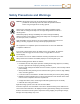
DIGITAL CONTROL INCORPORATED Safety Precautions and Warnings Warning All operators must read and understand the following safety precautions and warnings and must review this operator’s manual before using the DigiTrak F5 Locating System. Serious injury and death can result if underground drilling equipment makes contact with an underground utility such as a high-voltage electrical cable or a natural gas line.
DIGITAL CONTROL INCORPORATED EQUIPMENT AND BATTERY DISPOSAL. This symbol on equipment indicates that the equipment must not be disposed of with your other household waste. Instead, it is your responsibility to dispose of such equipment at a designated collection point for the recycling of batteries or electrical and electronic equipment. If the equipment contains a banned substance, the label will show the pollutant (Cd = Cadmium; Hg = Mercury; Pb = Lead) near this symbol.
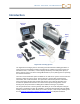
DIGITAL CONTROL INCORPORATED Introduction FSD remote display Receiver Battery packs Battery charger Adapter and power cords for Battery charger Transmitters Brace insert DigiTrak F5 Locating System The DigiTrak F5 Locating System is used during horizontal directional drilling operations to locate and track a transmitter installed in the drill head.
DIGITAL CONTROL INCORPORATED The following sections describe each F5 system component—the receiver, transmitters, remote display, battery charger, and cable transmitter.
DIGITAL CONTROL INCORPORATED Receiver Display screen Toggle (thumb switch) Grip Handle Trigger switch Battery tab Serial number Battery compartment Front panel Telemetry frequency designation Boot F5 Receiver – Side and Back Views General Description The F5 receiver is a handheld unit used for locating, tracking, and mapping the path of an F5 or F Series transmitter.
DIGITAL CONTROL INCORPORATED Toggle and Trigger Switches The F5 receiver has two switches for operating the system: a toggle (thumb switch) located on the top of the unit and a trigger located under the handle. Toggle Switch Used to access and navigate menus. Moves in four directions: left, right, up (toward the display), and down (toward the handle). Trigger Switch Used to turn on the receiver (hold), to select menu options, and to change the screen view for depth readings.
DIGITAL CONTROL INCORPORATED To check the charge on the battery pack, push the battery status button located under the LEDs below the battery tab. The LEDs will illuminate to indicate the amount of charge remaining. See Battery Charger on page liv for more information. Power On To turn on the receiver, pull and hold the trigger switch for at least two seconds, then release.
DIGITAL CONTROL INCORPORATED Note If an item of the self-test fails, a warning displays and a failure message appears in place of the system name. For example, a new or reset receiver may display a message indicating a 10-ft calibration is required (see Calibrate Receiver to Transmitter on page 6). If the error is not addressed in this manual, please contact DCI Customer Service. Using the Keypad A keypad is provided in several menus for entering values at the receiver.
DIGITAL CONTROL INCORPORATED Receiver battery status (shown fully charged) Telemetry channel Transmitter Selection type and frequency Locate Mode (blue background indicates option is highlighted for selection) Calibration Menu Settings Menu Power Off Height-Above-Ground (HAG) Menu Transmitter Selection Menu Down arrow indicates more options below (toggle down to view) Description of highlighted option Receiver Main Menu, First Screen System Info Menu Drill DataLog Menu Diagnostics Menu Pressure-
DIGITAL CONTROL INCORPORATED screen is the default screen for locating and where transmitter data is displayed. When the receiver is detecting a signal from a transmitter, the Locate Mode screen provides real-time data about the transmitter’s location, temperature, pitch, roll, fluid pressure (when a fluid pressure transmitter is used), and signal strength. See Locate Mode Screen on page xxviii for more information. Power Off Select Power Off to turn the receiver off.
DIGITAL CONTROL INCORPORATED Pitch Units Menu Depth Units Menu (shown highlighted) Set Time and Calendar Roll Offset Menu Telemetry Channel Menu Pressure Units Menu Current setting of highlighted option Receiver Settings Menu, First Screen Temperature Units Menu Language Selection Menu Force Units Menu Exit Current setting of highlighted option Receiver Settings Menu, Second Screen Any changes made to settings will be saved when the receiver is turned off.
DIGITAL CONTROL INCORPORATED Note The temperature units are determined by the depth units selected. Celsius (°C) temperature units will display for metric, and Fahrenheit (°F) temperature units will display for English (feet only, inches only, or feet and inches). Pitch Units Menu Use this menu to choose between two options: percent (x%) and degrees (x°).Toggle to and click your preference. The confirmation signal will sound as the screen returns to the settings menu.
DIGITAL CONTROL INCORPORATED 2. Enter the date one digit at a time from left to right. The date format is two digits for the month, two digits for the day, and four digits for the year (MM/DD/YYYY). For example, to set the date to January 2, 2013 (01/02/2013), toggle to highlight the “0”, click the trigger to select it, then do the same for 1, 0, 2, 2, 0, 1, and 3. 3. Toggle to the blue return arrow and click the trigger. The confirmation signal will sound as the screen returns to the Settings menu.
DIGITAL CONTROL INCORPORATED Transmitter Selection Menu This menu allows you to specify the transmitter type, model, and frequency, when applicable.
DIGITAL CONTROL INCORPORATED Set up drill DataLog job (shown highlighted) Delete drill DataLog job or jobs Add survey point Upload drill DataLog job to a computer Enable/disable drill DataLog function (green if enabled, red if disabled) View drill DataLog jobs Description of highlighted option Drill DataLog Menu, First Screen Exit Will read “Disabled, click to enable” if logging is disabled Drill DataLog Menu, Second Screen The LWD software has a variety of options for analyzing, editing, displayin
DIGITAL CONTROL INCORPORATED Place the receiver on generally level ground and click the trigger on the green icon. The ground does not have to be perfectly level. To cancel the level check and return to the main menu at any time, click Exit. Continue Exit Level Test Screen 1 Rotate the receiver 180 degrees so it faces the opposite direction as illustrated by the icon on the screen and click the trigger on the green icon again.
DIGITAL CONTROL INCORPORATED If the level check fails, the receiver beeps twice and displays an error screen: Retry Exit Level Test Failed Screen Click Retry and repeat the test as described above. If the check fails again, contact DCI Customer Service. Perform System Self-Test Select this option to perform a system self-test.
DIGITAL CONTROL INCORPORATED Test Progress Screen 4. At the conclusion of a successful test, the receiver beeps four times and the locate screen displays with no errors. Successful Signal Self-Test Screen Potential test failures Background noise If the test begins in an area with too much background noise, the test stops and the receiver displays a warning similar to Background signal is too high. Find a lower-noise area and try the test again.
DIGITAL CONTROL INCORPORATED DSP channel failure In the event of a Digital Signal Processor (DSP) channel failure, the receiver displays the error message Critical: DSP channels on the locate screen and locks the receiver. Contact DCI Customer Service. System Info Menu Displays technical system information such as ID, region, and firmware version. Use the toggle or trigger to exit to the main menu.
DIGITAL CONTROL INCORPORATED The pressure-tension (P-T) DataLog menu is used with fluid pressure transmitters and the TensiTrak transmitter. It appears as shown below when the P-T DataLog function is disabled, which is the default setting. To enable the function, select the red enable/disable P-T DataLog function icon shown below; the icon will change to green.
DIGITAL CONTROL INCORPORATED display returns to the Locate Mode screen with data recording turned off.
DIGITAL CONTROL INCORPORATED Locate Mode Screen The first option in the main menu is Locate Mode, which displays the Locate Mode screen. When the receiver is detecting a signal from a transmitter, the Locate Mode screen provides real-time data about the transmitter’s location, temperature, pitch, roll, and signal strength.
DIGITAL CONTROL INCORPORATED When using a fluid pressure (P-T) transmitter, the Locate Mode screen has an additional data field and recording symbol: Recording symbol indicates that P-T data is being recorded Fluid pressure on transmitter (displays in kPa when using metric units) Locate Mode Screen with Fluid Pressure Data (Trigger Released) When using a TensiTrak monitoring system during the pullback process, the Locate Mode screen displays the annular mud pressure, pullback force, and number of data p
DIGITAL CONTROL INCORPORATED Predicted Depth Screen The predicted depth screen displays when the receiver is positioned at the front or rear locate point (FLP or RLP) and the trigger is held in. The predicted depth is the depth the transmitter is calculated to be at when it reaches the front locate point if it continues on its current trajectory. The predicted depth is only valid at the FLP. See Locating on page 15 for more information.
DIGITAL CONTROL INCORPORATED Standard Receiver Screen Symbols Transmitter Roll – Shows the transmitter’s roll position. A line points to the roll position, and the roll value appears in the center of the clock. The number of roll positions is a function of the transmitter (12 or 24). When roll offset is used, the letters “RO” appear at the bottom left. Warning – Appears when there has been a failure in the self-test.
DIGITAL CONTROL INCORPORATED Standard Receiver Screen Symbols Receiver Battery – Depicts the remaining battery life of the receiver (shown 80% full here). When empty, the icon will flash in the Locate Mode screen , signifying that it is critical to change the battery immediately. Dual Transmitter Symbol – Appears to the upper left of the transmitter roll icon when the receiver is set for an F5 12 kHz or dual transmitter and a transmitter in dual mode is detected.
DIGITAL CONTROL INCORPORATED Transmitters A transmitter fits inside the drill housing and generates a magnetic field that the F5 receiver detects. The F5 receiver must be set to match the frequency of the transmitter. The receiver must also be calibrated to the transmitter before drilling and the calibration must be verified (see on page 3). The transmitter and receiver must have matching regional designation numbers to communicate with each other and comply with local operating requirements.
DIGITAL CONTROL INCORPORATED The short-range FS transmitter has a depth range of approximately 15 ft (4.6 m). It measures 8 in. (20.32 cm) long and 1.00 in. (2.54 cm) in diameter and broadcasts at 12 kHz. Index slot Temp dot Regional designation number Short-Range FS Transmitter The High Interference Immunity Transmitter (PulseTrak) for F5 measures 15 in. (38.1 cm) long and 1.25 in. (3.175 cm) in diameter and has a depth range of approximately ____ ft (____ m).
DIGITAL CONTROL INCORPORATED Battery cap Fluid pressure sensor ports (clean after use) Front end cap Long-Range Fluid Pressure Transmitter (FPT) For complete instructions on using the DataLog system for recording pressure-tension data, please see the DigiTrak LWD DataLog System Operator’s Manual. For a list of all current DigiTrak Transmitters, see Transmitter Selection on page xxxix.
DIGITAL CONTROL INCORPORATED Note ™ Do NOT use the battery contact spring at either end of a single SuperCell battery. 3.6 V Select the frequency of a dual-frequency transmitter by installing the batteries with the transmitter pointing either up or down: Load batteries with transmitter pointing up Load batteries with transmitter pointing down 1.5 V SuperCell 1.5 V 1.5 V To operate F5D 19/12 or F5Dp 19/12 transmitter in high-frequency mode (19.2 kHz) 1.5 V or SuperCell To operate F5D 12/1.
DIGITAL CONTROL INCORPORATED Transmitter Battery Status The battery status symbol at the bottom of the receiver’s depth mode screen indicates the battery life remaining for alkaline batteries. Because the battery status for a SuperCell battery will appear full until just before it is fully depleted, you must track its hours of use.
DIGITAL CONTROL INCORPORATED Slots for extended long-range transmitters (19 in./48.26 cm long) must be at least 13 in. (33 cm) long and begin at least 2 in. (5.1 cm) but not more than 3 in. (7.6 cm) from the front of the transmitter: Slot position Battery compartment Front end Slot length 13 in. (33 cm) 2 in. (5.1 cm) Extended Long-Range Transmitter Housing Slot Requirements Slots for the short-range FS transmitter (8 in./20.32 cm long) must be at least 3.75 in. (9.5 cm) long and begin at least 1.
DIGITAL CONTROL INCORPORATED properly when you install the transmitter in the drill housing, you will need to Set Roll Offset (see page 11). Transmitter Selection For the receiver to detect the signal from the transmitter, the receiver and transmitter must have matching regional designation numbers (see Receiver Startup Screen image on page xiii).
DIGITAL CONTROL INCORPORATED Transmitter Selection Menu Options Menu Option PN/Model Frequency PN: F5D 19/12 HDT Menu Option PN/Model Frequency 19.2 kHz PN: FC FC 12 kHz (cable) PN: F5D 19/12 HDT 12 kHz PN: F5Dp 19/12 FPT 19.2 kHz PN: F5D 12/1.3 HDT Single High (SH) at 12 kHz PN: F5Dp 19/12 FPT 12 kHz PN: F5D 12/1.3 HDT Dual High (DH) at 12 kHz PN: F5Dp 12/1.3 FPT Single High (SH) at 12 kHz PN: F5D 12/1.3 HDT Dual Low (DL) at 1.3 kHz PN: F5Dp 12/1.
DIGITAL CONTROL INCORPORATED Once an option is selected, the screen will return to the main menu with the type and frequency of the selected transmitter displayed at the top of the screen. If a new transmitter option is selected, calibration will be required. Calibration is not required, however, when switching between transmitters that were previously calibrated. Calibration is required every time a new transmitter, receiver, or different housing is used. Note When using a “12/1.
DIGITAL CONTROL INCORPORATED 3. Slowly roll the transmitter clockwise to its 2 o’clock position (± one-half clock position) and allow it to remain there for 10–18 seconds. 4. Slowly roll the transmitter clockwise to its 7 o’clock position (± one-half clock position). 5. When transmitter data disappears from the receiver, the transmitter frequency has changed (this will take approximately 10–18 seconds). 6.
DIGITAL CONTROL INCORPORATED Temperature Warning Tones 118–133° F (48–56° C) Three double-beep sequences (beep-beep, beep-beep, beep-beep) for every 4° C increase in temperature. Cooling is critical to avoid irreversible damage. Above 140° F (60° C) Three double-beep sequences every 5 seconds on the remote display, and every 20 seconds on the receiver.THis warning signifies dangerous drilling conditions; irreversible damage may have already been done.
DIGITAL CONTROL INCORPORATED Remote Display Removable visor Keypad Antenna Direction buttons Display screen Serial number Telemetry frequency designations Execute button Battery pack or brace insert DigiTrak F Series Display M (FSD) Front and Back a g n e t The DigiTrak F Series Display (FSD) is a multifunction remote used with a variety of DigiTrak i receivers. It provides the drill rig operator with information from the receiver about the depth, c orientation, and status of the transmitter.
DIGITAL CONTROL INCORPORATED Connecting the DC Power Cable The DC power port and DC power cable connector are keyed for proper alignment. To connect the power cable, remove the protective cap from the power port on the back of the remote, align the key marks in the connector with the key slots in the power port, and push in and rotate the connector clockwise until the connector locks into place. Connect the other end of the DC cable to a DC power source.
DIGITAL CONTROL INCORPORATED Execute Button Use to turn on the FSD unit, select a highlighted menu option, adjust contrast, and execute menu options. Functions like the trigger switch on the receiver. Direction Buttons Use to navigate through menu options. Use the down button to access the main menu from the remote mode. The direction buttons function like the toggle switch on the receiver.
DIGITAL CONTROL INCORPORATED Caution Adjusting the up/down orientation of the display without loosening the knobs can damage the unit. Squeeze knobs Loosen Display Knobs Adjust Viewing Angle Left/Right When the FSD remote’s magnetic base is secure, you can adjust the left-right viewing angle by rotating the display about the base. Center Tighten Display Knobs Rotation for center viewing adjustment Ridge With the magnetic base secure, take hold of the display and rotate it to the desired orientation.
DIGITAL CONTROL INCORPORATED Main Menu Access the main menu by pushing the down arrow button. The Remote Mode option is automatically highlighted. Power Off Remote Mode (shown highlighted) Settings Adjust Contrast Information Description of highlighted option Cable Mode FSD Main Menu Screen Use the arrow buttons to highlight an option, then press the execute button to select it. The options available on the main menu are described below and in the following sections.
DIGITAL CONTROL INCORPORATED Settings Settings lets you change the settings shown below: Telemetry frequency designation Telemetry channel (shown highlighted) Receiver model Exit Depth units Description of highlighted option Pitch units FSD Settings Menu Changes made to these settings won’t be saved until the FSD remote is turned off. DCI recommends that you set the FSD remote settings to match those on your receiver.
DIGITAL CONTROL INCORPORATED Pitch Units Lets you set pitch angle units as either percent (%) or degree (°). Exit Exits the Settings menu and returns to the main menu. If a setting was changed, the exit option is automatically highlighted.
DIGITAL CONTROL INCORPORATED Display Screens Main Screen The main screen is the default screen displayed on startup. It shows the transmitter pitch, roll, battery status, depth, predicted depth, and temperature. The main screen also shows the FSD battery status, receiver type, telemetry channel, telemetry update meter, and Target Steering data (if active). To exit this screen, press the down arrow button to return to the main menu.
DIGITAL CONTROL INCORPORATED When the receiver is positioned at the LL with the trigger held in, the FSD display will change to show the depth reading, with arrows pointing to the ground and drill head. When the height-above-ground function (HAG) is turned on, the receiver icon is shown elevated above the ground with the HAG setting displayed. The following figure shows the HAG setting at 2' 03", indicating the receiver is being held that distance above the ground.
DIGITAL CONTROL INCORPORATED Predicted Depth Screen The predicted depth screen appears when the receiver is positioned at the front or rear locate point (FLP or RLP) and the trigger is held in. However, the predicted depth is only valid at the FLP. The predicted depth display will show arrows pointing to the receiver and the predicted depth point ahead of the transmitter. For more information about predicted depth, see Locating on page 15.
DIGITAL CONTROL INCORPORATED Battery Charger AC adapter F Series battery charger F Series battery packs AC power cord DC power cord F Series Battery Charger System General Description The DigiTrak F Series Battery Charger (FBC) system includes AC and DC power cords, an AC adapter, and three rechargeable F Series battery packs. The battery packs power both the F5 receiver and the FSD remote. The FBC battery charger can operate from AC (100– 240 V, 50–60 Hz, 1.5 A max.) or DC (10–28 V, 5 A max.
DIGITAL CONTROL INCORPORATED AC/DC Power Setup Install either the AC adapter or the DC power cord by inserting the charger plug into the power port of the battery charger and then rotating it a quarter turn in either direction to lock it in place. Green LED Charger plug If using AC power, connect the AC power cord to the AC adapter, then plug the adapter into an AC power receptacle. If using DC power, plug the DC power cord directly into the DC power source.
DIGITAL CONTROL INCORPORATED LEDs and Audible Signals Charger or Battery Pack Status Status Description Action Flashing Orange No Battery Pack Detected No battery pack or unknown battery type detected. Insert viable battery pack. Solid Green & Solid Orange Slow Charge / Voltage Restoration Battery pack voltage is less than 11.0 V, or Battery pack temperature is above 104° F (40° C). None. Charger will slowly restore battery pack to full voltage.
DIGITAL CONTROL INCORPORATED Warning If you transport the charger in checked baggage, be sure to remove the batteries from the charger before packing it. Temperature The temperature of the air around the battery charger should be between +32° to +95° F (0° to +35° C). Charging the battery outside this range may increase charge time, harm battery performance, or reduce battery life. It is important to maintain free airflow around the charger, especially near the top and bottom vents.
DIGITAL CONTROL INCORPORATED Getting Started This section details the basic steps required to set up the F5 locating system and prepare for locating.
DIGITAL CONTROL INCORPORATED 5. From the main menu, select the Settings menu to set the depth units, pitch units, and telemetry channel. Ensure you use the same settings here as you are on the receiver. You should also use the same system of units (English or metric) on both devices. Transmitter 1. Compare the regional designation number on the transmitter with the number on the receiver’s serial number label. If they don’t match, contact DCI Customer Service. 2.
LL DIGITAL CONTROL INCORPORATED Red flag area Intended bore path Background noise One-Person Background Signal Strength Check (No Transmitter) Roll/Pitch Check LL At the end of the bore path, turn the receiver to face toward the launch end, and install batteries in the transmitter to turn it on. Have a coworker hold the transmitter and stand beside you approximately 1.5 times the maximum depth of your intended bore.
DIGITAL CONTROL INCORPORATED Suggestions for Dealing with Interference If pitch/roll information becomes erratic or is lost, move the receiver away from the interference source while staying within range of the transmitter. Separation (use of the HAG function; see page 13) of the receiver from both passive and active interference is known to reduce or eliminate interference-related problems. Another option is to use a transmitter with a different frequency or greater depth range.
DIGITAL CONTROL INCORPORATED Do not calibrate if: You are within 10 ft (3 m) of metal structures, such as steel pipe, chain-link fence, metal siding, construction equipment, automobiles, etc. The receiver is over rebar or underground utilities. The receiver is in the vicinity of excessive electrical interference. The signal strength from the transmitter is less than 300 points (too low) or greater than 950 points (too high).
DIGITAL CONTROL INCORPORATED 3. From the main menu, select Calibration, then the 1-point calibration option. 10′ (or 3 m) Continue 1-point calibration (shown highlighted) Exit (returns to main menu) 1-Point Calibration Screen 4. Click the trigger on Continue to initiate calibration. The screen will show that the receiver is calibrating. Do not move the receiver. Calibration-In-Progress Screen 5.
DIGITAL CONTROL INCORPORATED Note If depth data does not display, you will need to obtain a reference lock (“R”). See discussion under Finding the Front Locate Point (FLP) on page 19. 2-Point Calibration (In Ground) The 2-point calibration procedure is rarely needed. It requires you to obtain two calibration points, one with the receiver placed on the ground and one with the receiver raised 3 ft (or 1 m) above the ground.
DIGITAL CONTROL INCORPORATED ( o r 1 m ) 2-Point Calibration, Obtain 2 nd Point 7. Lift the receiver 3 ft (or 1 m) directly up and click the trigger to initiate calibration of the second calibration point. The calibration-in-progress screen displays again. Do not move the receiver. 8. Once the second point is obtained, the confirmation signal will sound and a checkmark will display on the screen, indicating a successful calibration. The screen will then return to the Locate Mode screen.
DIGITAL CONTROL INCORPORATED View Calibration Use this option to check the most recent calibrations for your transmitter(s). The data will include the model of transmitter, type of calibration (1-point or 2-point), signal strength, and a timestamp. Though this window lists all transmitters compatible with the F5 receiver, only transmitters calibrated to your receiver will display data in the Signal and Timestamp columns. View Calibration Window Toggle down to view additional pages.
DIGITAL CONTROL INCORPORATED If you cannot align the 12 o’clock position of the transmitter to that of the drill head, you will need to set and enable the roll offset function. The roll offset function electronically compensates to match the transmitter’s 12 o’clock position to that of the drill head. To set roll offset, at the receiver main menu, select Settings, then Roll Offset . Enable Roll Offset 1. Select Set and enable roll offset from the Roll Offset menu.
DIGITAL CONTROL INCORPORATED If the receiver does not detect a roll signal from the transmitter, the roll offset operation fails: Roll Offset Failure Screen Click the trigger to retry setting the roll offset or toggle right to select exit and return to the settings menu. If the roll offset failure screen appears, verify the setup and try again or contact DCI Customer Service. Disable Roll Offset To turn off the roll offset function, select the disable roll offset option from the roll offset menu.
DIGITAL CONTROL INCORPORATED 2. From the receiver main menu, select the HAG menu option. You will see the HAG menu with the enable option highlighted for selection and the current or default (12 in. or 0.30 m) HAG setting shown in the description line at the bottom of the screen. If the HAG had previously been enabled, the disable option would show automatically highlighted for selection.
DIGITAL CONTROL INCORPORATED Locating Locating in High-Interference Area with the F5 Receiver Locating with the F5 system is relatively easy and intuitive, but you must understand some locating basics first. This section explains the front and rear locate points (FLP and RLP) and locate line (LL), the geometry of these elements with respect to the transmitter, and the proper method for marking locate points.
DIGITAL CONTROL INCORPORATED Locating Basics Locate Points (FLP & RLP) and Locate Line (LL) The F5 receiver locates the transmitter by detecting three specific places in the transmitter’s magnetic field: the locate points and the locate line. The locate points are indistinguishable from one another by the receiver. They represent similar points in the transmitter’s field in front of and behind the transmitter.
DIGITAL CONTROL INCORPORATED Note If the transmitter pitch exceeds ±30% (or ±17°) and/or the transmitter depth exceeds 15 ft (4.6 m), the position of the locate line will be somewhat ahead of or behind the transmitter’s actual position. In these cases, the depth displayed on the receiver is referred to as the projected depth. Appendix B on page 37 provides more information regarding this situation.
DIGITAL CONTROL INCORPORATED Marking Locate Points The locate points (FLP and RLP) and the locate line (LL) must be found and accurately marked during the locating procedure. To mark a locate point, stand with the receiver level at the locate point. Look down the vertical axis that runs through the center of the display to project a plumb line to the ground (see figure below). Mark where this plumb line hits the ground .
DIGITAL CONTROL INCORPORATED Standard Method for Locating the Transmitter With the F5 system, you can locate the transmitter and its heading while it moves, whether standing in front of it, behind it, or toward the side. You can also locate the transmitter facing either toward or away from the drill rig. The standard method described in this section guides you to the transmitter while standing in front of it, facing the drill rig. This is the recommended method for locating.
DIGITAL CONTROL INCORPORATED The FLP will be found further out in front of the drill head as the drill head gets deeper. 3. Observe the position of the locating target ( ) relative to the receiver box on the display. The figures below illustrate what you might see on the display and the actual position of the receiver, transmitter, and locate points. Note that the FLP is ahead of and to the left of the receiver, as shown in the receiver display.
DIGITAL CONTROL INCORPORATED Reference signal set Target-inthe-box Receiver Depth Mode Screen (at FLP with HAG on) Actual Position of Receiver and Transmitter Warning Do not hold the trigger in unless you are precisely at the FLP (target centered in box). If you are ahead of the FLP, you could set an incorrect reference that causes a ghost locate line. In this case, you must reference again at the FLP.
DIGITAL CONTROL INCORPORATED Finding the Locate Line (LL) 7. Continue to walk in the direction of the drill or the last known transmitter location. Keep the locating target on the vertical crosshair and observe that the signal strength is increasing. Signal strength higher than value at FLP Locating target aligned with vertical crosshair Receiver Locate Mode Screen (FLP Behind Receiver, Which Is Moving Toward LL) If the signal strength decreases, you may actually have just located the RLP.
DIGITAL CONTROL INCORPORATED Locate line (red when not aligned in box for depth reading) Yaw (left/right rotation of transmitter relative to receiver) Receiver Locate Mode Screen (Approaching LL) Actual Position of Receiver and Transmitter Do not rely on the alignment of the ball with the vertical crosshair to identify the left/right position of the transmitter.
DIGITAL CONTROL INCORPORATED Finding the RLP to Confirm Transmitter Heading and Position Finding the RLP will allow you to confirm the transmitter’s heading and position. Like the FLP, the RLP is represented as a target ( ) on the receiver display. Continue the locating procedure as follows: 11. From the LL, facing toward the drill or last transmitter location, walk forward while keeping the target aligned on the vertical crosshairs.
DIGITAL CONTROL INCORPORATED 14. A line between the RLP and FLP represents the transmitter’s heading. The transmitter is located beneath where this line and the LL cross. 15. Position the receiver at the intersection of these lines with the LL passing through the center of the box on the display and hold the trigger to take a depth reading.
DIGITAL CONTROL INCORPORATED Tracking “On-the-Fly” If you are running at 0% (0°) pitch over level ground, the predicted depth will be the actual depth. In this case, all locating can be done at the FLP while the tool is moving.
DIGITAL CONTROL INCORPORATED Receiver Screen Tracking "On-the-Fly" Actual Position of Receiver and Transmitter As the drill head advances, the FLP should travel along the receiver’s vertical crosshairs, indicating that the tool is still on line. Once the FLP is in the box, hold the trigger in and confirm that the predicted depth reading is as expected.
DIGITAL CONTROL INCORPORATED Bore path Obstruction Path around obstruction LL P1 P2 P3 Predetermined distances D r i Preparing for l Off-Track Locating l 3. While still holding the trigger in and keeping the receiver in the same orientation, step to the side of the tool another predetermined distance (P2) further away from it. Move the receiver forward and aft until you can see the ball jump from the bottom of the screen to the top of the screen (or vice versa), then mark this location. 4.
DIGITAL CONTROL INCORPORATED Differences in pitch will also affect the signal strength and slant distance as the tool progresses.
DIGITAL CONTROL INCORPORATED Target Steering Target Steering allows the F5 receiver to be placed ahead of the drill head and used as a steering target. Position the receiver on level ground so it is facing in the same direction as the drilling. To activate Target Steering, you must program the receiver with the desired target depth. The drill head can then be guided to a point directly below where the receiver has been placed using the Target Steering screen on the remote display.
DIGITAL CONTROL INCORPORATED The Target Steering procedure requires correct placement of the receiver. Place the receiver less than 35 ft (10.7 m) in front of the transmitter on the bore path with its back end (where the battery pack is inserted) facing the drill (or the last locate point, if drilling a curved path). Programming the Receiver for Target Steering The receiver must be programmed with the desired target depth using the Target Steering menu.
DIGITAL CONTROL INCORPORATED Roll indicator Roll/pitch update meter Transmitter pitch Locating target (FLP) Approximate transmitter depth Horizontal distance between transmitter and receiver Transmitter temperature Target Steering Locate Mode Screen Pressure data for a fluid pressure sensing transmitter will display in a field between the transmitter pitch and approximate transmitter depth.
DIGITAL CONTROL INCORPORATED The following image shows the side view of the position of the receiver and the transmitter on the left and an end view of the same setup on the right.
DIGITAL CONTROL INCORPORATED Turn Off Target Steering To turn off Target Steering, toggle down from the Target Steering Locate Mode screen to return to the standard locate mode display. The receiver will now no longer act as a steering target.
DIGITAL CONTROL INCORPORATED Appendix A: System Specifications and Maintenance Requirements The power requirements, environmental requirements, and equipment maintenance requirements for the DigiTrak F5 Locating System are listed below. Power Requirements Device (Model Number) Operational Voltage Operational Current DigiTrak F5 Receiver (F5R) 14.4 V (nominal) 350 mA max DigiTrak F Series Display (FSD) 14.4 V (nominal) 220 mA max DigiTrak F Series Battery Charger (FBC) Input 10–28 V Output 19.
DIGITAL CONTROL INCORPORATED General Transmitter Care Instructions Periodically clean the spring and threads inside the battery compartment as well as the spring and threads of the battery end cap to ensure a proper power connection with the batteries. Use an emery cloth or wire brush to remove any oxidation that has built up. Be careful not to damage the battery cap O-ring; remove it while cleaning if necessary.
DIGITAL CONTROL INCORPORATED Appendix B: Projected Depth Versus Actual Depth and the Fore/Aft Offset What Happens When the Transmitter Is Steep and Deep The signal field emitted by the transmitter, as shown in Figure B1, consists of a set of elliptical signals, or “flux lines”. The flux lines indicate the position of the transmitter.
DIGITAL CONTROL INCORPORATED Due to the shape of the transmitter’s signal field, when it is at a pitch greater than ±30% (±17°) and/or a depth of 15 ft (4.6 m) or more, the position of the locate line will be some distance ahead of or behind the transmitter’s actual position. In this case, the depth displayed on the receiver becomes what is called the projected depth. The transmitter’s distance ahead of or behind the locate line is called the fore/aft offset.
DIGITAL CONTROL INCORPORATED Using the tables provided below, you can look up the actual depth (Table B1) and the fore/aft offset (Table B2) based on the receiver’s depth reading (projected depth) and the transmitter pitch. You can also look up the projected depth (Table B3) if you know the required depth (actual depth) of your installation and you want to find the corresponding projected depth reading that you will see on the receiver during drilling.
DIGITAL CONTROL INCORPORATED Table B2 lists the projected or displayed depth values in 5 ft (1.52 m) increments in the first column and provides values for the fore/aft offset (shown in purple), rounded to the nearest inch (or cm) at different transmitter pitches. Table B2. Determining Fore/Aft Offset from Displayed (Projected) Depth and Pitch Pitch→ ±10% (5.7°) ±20% (11°) ±30% (17°) ±40% (22°) ±50% (27°) ±60% (31°) ±75% (37°) ±90% (42°) ±100% (45°) 5' (1.52 m) 4" (0.10 m) 8" (0.20 m) 11" (0.
DIGITAL CONTROL INCORPORATED Table B3 lists the actual depths in 5 ft (1.52 m) increments in the first column and provides projected depth values at different transmitter pitches. Table B3. Determining Projected Depth from Actual Depth and Pitch Pitch→ Actual Depth ↓ ±10% (5.7°) ±20% (11°) ±30% (17°) ±40% (22°) ±50% (27°) ±60% (31°) ±75% (37°) ±90% (42°) ±100% (45°) 5' (1.52 m) 5' (1.52 m) 5' 2" (1.57 m) 5' 3" (1.60 m) 5' 6" (1.68 m) 5' 8" (1.73 m) 5' 11" (1.80 m) 6' 3" (1.91 m) 6' 6" (1.
DIGITAL CONTROL INCORPORATED and you will find that your receiver’s projected depth reading at the locate line should display as 25 ft 5 in. (7.75 m). Using the projected depth displayed on your receiver, you can calculate the actual depth of the transmitter using the second row of conversion factors. Select the corresponding conversion factor associated with your pitch value, then multiply that value by the projected depth. For example, if your pitch is 30% and your projected depth reading is 24 ft (7.
DIGITAL CONTROL INCORPORATED Appendix C: Calculating Depth Based on Distance Between FLP and RLP It is possible to estimate the transmitter depth should the information displayed on the receiver become unreliable. This is only possible if you know the transmitter pitch and the positions of the front locate point (FLP) and the rear locate point (RLP) and if the ground surface is level. To estimate the transmitter depth, first measure the distance between the FLP and the RLP.
DIGITAL CONTROL INCORPORATED 44 Pitch ( % / ° ) Divider Pitch ( % / ° ) Divider Pitch ( % / ° ) Divider 32 / 17.7 1.49 66 / 33.4 1.73 100 / 45.0 2.
DIGITAL CONTROL INCORPORATED Appendix D: Reference Tables Depth Increase in Inches (Centimeters) per 10-foot (3-meter) Rod Percent Depth Increase Percent Depth Increase 1 1 (2) 28 32 (81) 2 2 (5) 29 33 (84) 3 4 (10) 30 34 (86) 4 5 (13) 31 36 (91) 5 6 (15) 32 37 (94) 6 7 (18) 33 38 (97) 7 8 (20) 34 39 (99) 8 10 (25) 35 40 (102) 9 11 (28) 36 41 (104) 10 12 (30) 37 42 (107) 11 13 (33) 38 43 (109) 12 14 (36) 39 44 (112) 13 15 (38) 40 45 (114) 14 17 (43)
DIGITAL CONTROL INCORPORATED Depth Increase in Inches (Centimeters) per 15-foot (4.
DIGITAL CONTROL INCORPORATED LIMITED WARRANTY Digital Control Incorporated ("DCI") warrants that when shipped from DCI each DCI Product will conform to DCI’s current published specifications in existence at the time of shipment and will be free, for the warranty period (“Warranty Period”) described below, from defects in materials and workmanship.
DIGITAL CONTROL INCORPORATED LIMITATION OF REMEDIES AND LIABILITY In no event shall DCI or anyone else involved in the creation, production, or delivery of the DCI Product be liable for any damages arising out of the use or inability to use the DCI Product, including but not limited to indirect, special, incidental, or consequential damages, or for any cover, loss of information, profit, revenue or use, based upon any claim by User for breach of warranty, breach of contract, negligence, strict liability, o