
User Manual
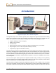

Table Of Contents
- Operator’s Manual
- Digital
- Control
- Incorporated
- Safety Precautions and Warnings
- Introduction
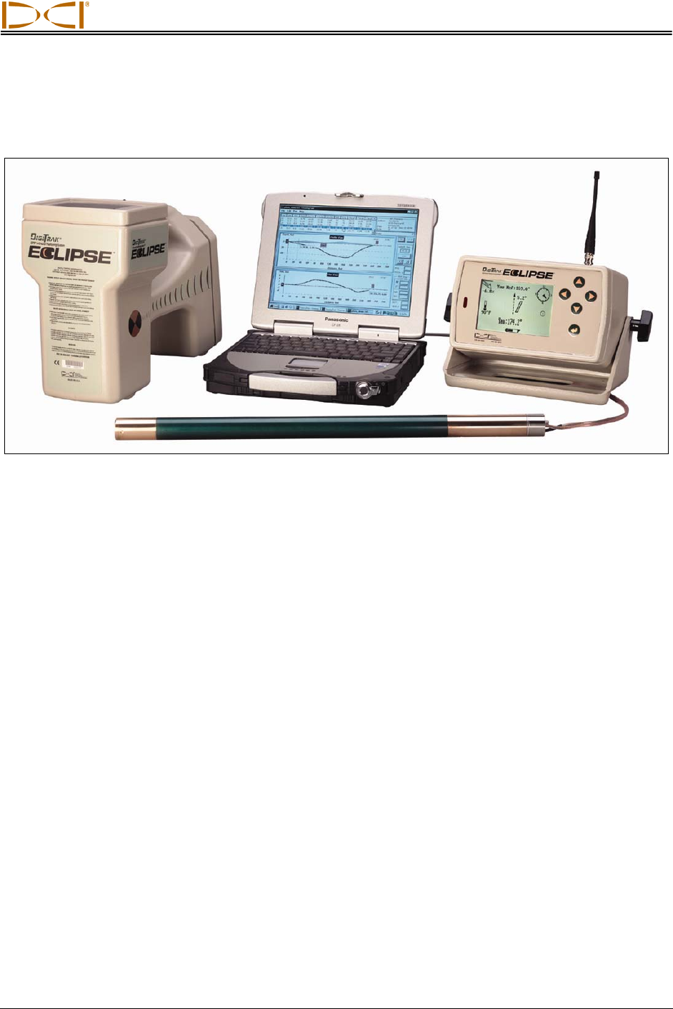
- System Components
- Startup and Operating Instructions
- SST Operating Procedure
- Setting Up SST Laptop
- Setting Up Equipment and Site
- 2. Establish Borepath Reference Line and Mark Borepath
- 3. Assemble and Torque-up Non-Magnetic Housing to Non-Mag Tool
- 4. Align Drill to Marked Borepath
- 5. Position & Align Non-mag Tooling Assembly onto Marked Borepath
- 6. Stage SST Equipment and Power Sources Adjacent to Tooling Assembly
- 7. Power Up Eclipse SST Equipment
- 8. Measure SST Transmitter Current Draw
- 9. Install SST Transmitter into Aligned Non-mag Tooling Assembly
- Setting Reference Heading (Ref Yaw) and Roll Offset
- Calibrating SST Tool and Confirming Proper System Operation
- Logging Drill Run
- Summary of Basic Operating Procedure
- SST Operating Procedure
- Computer Software Instructions
- Inputting and Changing Drill Data
- APPENDIXImporting Topography, Drill Plan, and Planned Deviation from Excel File
- LIMITED WARRANTY
DIGITAL CONTROL INCORPORATED
Introduction
DigiTrak
®
Eclipse
®
SST
®
Guidance System
The DigiTrak
®
Eclipse
®
SST
®
Guidance System, which is designed for tough horizontal directional drilling
(HDD) projects, provides real-time tool information that enables accurate steering of the drill head. The
system, also referred to as the Steering Tool, displays and records the following types of data:
¾ Compass heading (in tenths of a degree)
¾ Depth (in feet or meters)
¾ Lateral deviation
¾ Pitch (in tenths of a percent or in tenths of a degree, with updates every 1.3 seconds)
¾ Roll (in degrees, from 0 to 360, with updates 3 times per second)
¾ Temperature (in degrees Fahrenheit or Celsius)
The data is shown in real time to the drill operator on the remote display via the wireline connection. Real-
time data is also displayed on the laptop computer, which can be located up to 50 ft (15 m) away from the
remote display. The roll/pitch signal and depth signal, along with locate points, are also transmitted from
the SST transmitter for overhead locating using the receiver. DCI recommends that you use a combina-
tion of walkover and non-walkover locating whenever possible to increase the capabilities and accuracy
of the SST system.
Use of the SST system requires special non-magnetic downhole tooling, including a non-mag housing
and a non-mag 15-ft (3-m) length of drill pipe called a monel. If a mud motor is required, a second monel
will be used between the non-mag housing and the motor or bent sub.
The SST system is designed for jobs where walkover locating may not be an option, such as crossing
under a river or highway. The large amount of drill data that the system records enables reliable steering.
The system can also be used on projects where walkover locating is an option. In these cases, the SST
Eclipse
®
SST
®
Operator’s Manual 7