
User Manual

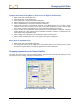
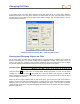
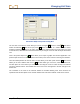

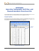
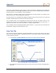
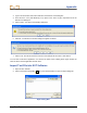
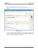
Table Of Contents
- Operator’s Manual
- Digital
- Control
- Incorporated
- Safety Precautions and Warnings
- Introduction
- System Components
- Startup and Operating Instructions
- SST Operating Procedure
- Setting Up SST Laptop
- Setting Up Equipment and Site
- 2. Establish Borepath Reference Line and Mark Borepath
- 3. Assemble and Torque-up Non-Magnetic Housing to Non-Mag Tool
- 4. Align Drill to Marked Borepath
- 5. Position & Align Non-mag Tooling Assembly onto Marked Borepath
- 6. Stage SST Equipment and Power Sources Adjacent to Tooling Assembly
- 7. Power Up Eclipse SST Equipment
- 8. Measure SST Transmitter Current Draw
- 9. Install SST Transmitter into Aligned Non-mag Tooling Assembly
- Setting Reference Heading (Ref Yaw) and Roll Offset
- Calibrating SST Tool and Confirming Proper System Operation
- Logging Drill Run
- Summary of Basic Operating Procedure
- SST Operating Procedure
- Computer Software Instructions
- Inputting and Changing Drill Data
- APPENDIXImporting Topography, Drill Plan, and Planned Deviation from Excel File
- LIMITED WARRANTY

Appendix
3. Select the file, after navigating to the folder where you saved it if necessary.
4. Click the Open button. You should see the three plotted profiles in the plot area of the SST
application.
Import of Text File
5. You may need to adjust the scaling. For example, the plots in the graphic above are compressed
to the left of the plot area. See “Graphing Options” in the Inputting and Changing Drill Data
section of the manual for information on how to edit the plots. For example, the graphic below
shows how the plots look after adjusting the Y Axis properties.
60 Eclipse
®
SST
®
Operator’s Manual