
User Manual

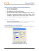

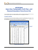
Table Of Contents
- Operator’s Manual
- Digital
- Control
- Incorporated
- Safety Precautions and Warnings
- Introduction
- System Components
- Startup and Operating Instructions
- SST Operating Procedure
- Setting Up SST Laptop
- Setting Up Equipment and Site
- 2. Establish Borepath Reference Line and Mark Borepath
- 3. Assemble and Torque-up Non-Magnetic Housing to Non-Mag Tool
- 4. Align Drill to Marked Borepath
- 5. Position & Align Non-mag Tooling Assembly onto Marked Borepath
- 6. Stage SST Equipment and Power Sources Adjacent to Tooling Assembly
- 7. Power Up Eclipse SST Equipment
- 8. Measure SST Transmitter Current Draw
- 9. Install SST Transmitter into Aligned Non-mag Tooling Assembly
- Setting Reference Heading (Ref Yaw) and Roll Offset
- Calibrating SST Tool and Confirming Proper System Operation
- Logging Drill Run
- Summary of Basic Operating Procedure
- SST Operating Procedure
- Computer Software Instructions
- Inputting and Changing Drill Data
- APPENDIXImporting Topography, Drill Plan, and Planned Deviation from Excel File
- LIMITED WARRANTY
DIGITAL CONTROL INCORPORATED
APPENDIX
Importing Topography, Drill Plan, and
Planned Deviation from Excel File
The SST software allows you to import topography, drill plan, and planned deviation data from a text file
created in Microsoft Excel. This should be done before you start logging your SST bore.
Create Text File
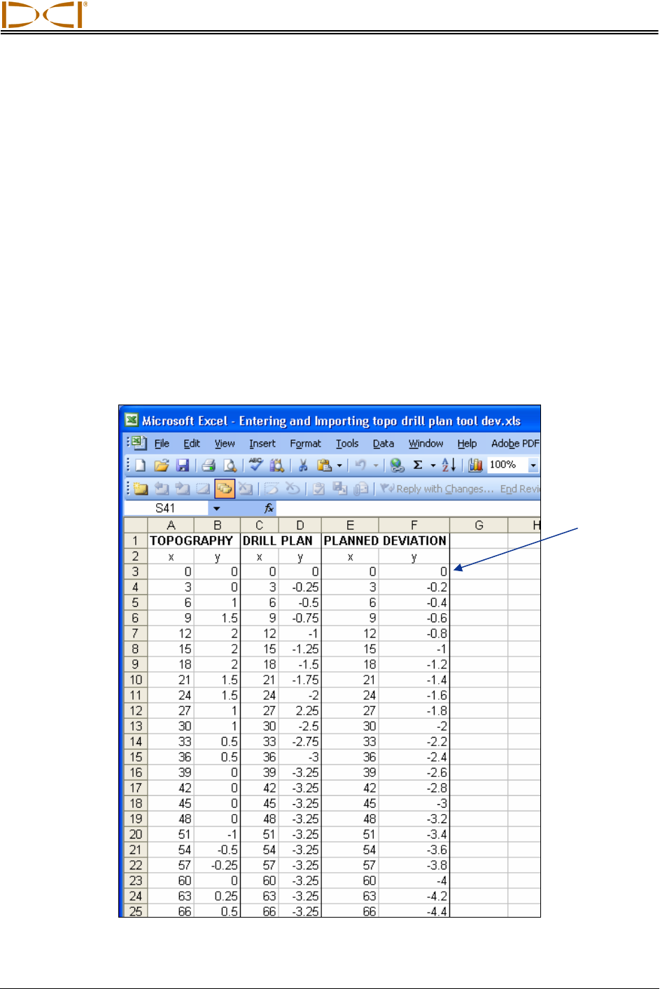
The file must be in the correct format for importing, as shown in the following figure. Each plot or set of
data (topography, drill plan, and planned deviation) spans two columns that list the x-coordinate in the
first column and the y-coordinate in the second column for each logged point.
First row
of data
Format for Data in Excel File
Eclipse
®
SST
®
Operator’s Manual 57