
User Manual

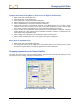
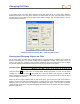
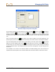

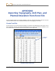
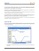
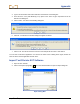
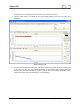
Table Of Contents
- Operator’s Manual
- Digital
- Control
- Incorporated
- Safety Precautions and Warnings
- Introduction
- System Components
- Startup and Operating Instructions
- SST Operating Procedure
- Setting Up SST Laptop
- Setting Up Equipment and Site
- 2. Establish Borepath Reference Line and Mark Borepath
- 3. Assemble and Torque-up Non-Magnetic Housing to Non-Mag Tool
- 4. Align Drill to Marked Borepath
- 5. Position & Align Non-mag Tooling Assembly onto Marked Borepath
- 6. Stage SST Equipment and Power Sources Adjacent to Tooling Assembly
- 7. Power Up Eclipse SST Equipment
- 8. Measure SST Transmitter Current Draw
- 9. Install SST Transmitter into Aligned Non-mag Tooling Assembly
- Setting Reference Heading (Ref Yaw) and Roll Offset
- Calibrating SST Tool and Confirming Proper System Operation
- Logging Drill Run
- Summary of Basic Operating Procedure
- SST Operating Procedure
- Computer Software Instructions
- Inputting and Changing Drill Data
- APPENDIXImporting Topography, Drill Plan, and Planned Deviation from Excel File
- LIMITED WARRANTY

Changing Drill Data
Annotation Object Properties Dialog Box
The next four icons after the cursor allow you to draw rectangles , circles or ovals , lines with or
without arrowheads
, and curved (arc) lines . These tools work in a similar manner to those
provided in drawing programs. To use them, click on the icon and then place the cursor where you want
to draw the item; click and hold in the mouse button as you drag the cursor to make the object the desired
size.
Next is the picture import icon
, which allows you to import a graphic from another application. The
picture import function is not activated (does not function) in the current version of Steering Tool software.
Then the toolbar provides two text box tools. The first allows you to draw a plain text box
. The second
allows you to draw a balloon with text in it
. To draw either type of text box, select the desired icon,
and then place the cursor where you want the box and drag the cursor to make the object the desired
size in the desired location. Then double-click on the word “Text” that appears in the box and type in the
desired text.
The remainder of the tools on the annotate toolbar are standard drawing tools. Their functions are
explained under the description of the annotate toolbar under “Plot Area Toolbars” earlier in this section.
Eclipse
®
SST
®
Operator’s Manual 55