
User Manual
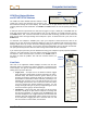
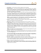
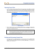
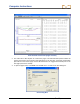
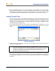
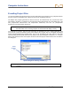
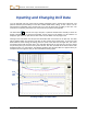
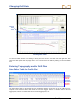
Table Of Contents
- Operator’s Manual
- Digital
- Control
- Incorporated
- Safety Precautions and Warnings
- Introduction
- System Components
- Startup and Operating Instructions
- SST Operating Procedure
- Setting Up SST Laptop
- Setting Up Equipment and Site
- 2. Establish Borepath Reference Line and Mark Borepath
- 3. Assemble and Torque-up Non-Magnetic Housing to Non-Mag Tool
- 4. Align Drill to Marked Borepath
- 5. Position & Align Non-mag Tooling Assembly onto Marked Borepath
- 6. Stage SST Equipment and Power Sources Adjacent to Tooling Assembly
- 7. Power Up Eclipse SST Equipment
- 8. Measure SST Transmitter Current Draw
- 9. Install SST Transmitter into Aligned Non-mag Tooling Assembly
- Setting Reference Heading (Ref Yaw) and Roll Offset
- Calibrating SST Tool and Confirming Proper System Operation
- Logging Drill Run
- Summary of Basic Operating Procedure
- SST Operating Procedure
- Computer Software Instructions
- Inputting and Changing Drill Data
- APPENDIXImporting Topography, Drill Plan, and Planned Deviation from Excel File
- LIMITED WARRANTY
Changing Drill Data
Entering Tool’s Planned Deviation
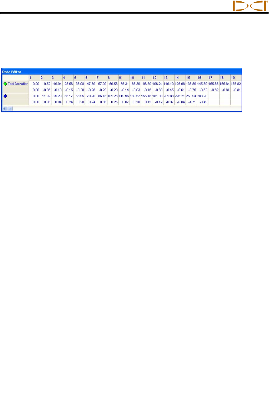
Data Editor Table for Deviation Plot
}
}
Computer
Generated
Manually
Entered
The Data Editor table for the Deviation plot has numbered columns across the top of the table that cor-
respond to the locations where data will be or has been logged, as in the table for the Profile plot. Column
1 contains data for the first logged point; column 2 contains data for the second logged point, etc. Note
that the first column will always have 0.00 in each cell, because the first point recorded on an SST bore is
when the tool is ½ in the ground and ½ out of the ground—referred to as the zero, zero point.
The deviation table has only two plotted profiles—Tool Deviation and an unnamed blank field, which you
should name appropriately (see below). There are two rows of values for each of these plotted profiles—
the upper row gives the x-coordinate or horizontal distance from the launch point, and the lower row gives
the y-coordinate or the distance above or below the zero elevation line or x-axis.
¾ Tool Deviation – These x,y coordinates are computer generated automatically by the SST
system’s software when you log the bore—you will not enter any information in these two rows.
¾ Unnamed or Blank – The x,y coordinates for this field are based on the launch point position and
are manually entered prior to, during, or after the bore. If the planned deviation is to the right of
the launch point (below the x-axis), you must enter a “–” sign, if the planned deviation is to the left
of the launch point (above the x-axis), you do not have to enter a “+” sign.
Naming Blank Field for Deviation Plot
The unnamed plotted profile field is left blank so that you can name it appropriately for your job. DCI
suggests something like Planned Deviation or Planned Line. To name this blank field, place the cursor in
the cell and double-click, then type the desired name and hit enter.
Entering or Changing Data for Planned Deviation Plot
To enter or change values for the x,y coordinates in the deviation table, double-click on a value and then
type in the new value and hit enter.
50 Eclipse
®
SST
®
Operator’s Manual