
User Manual
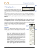
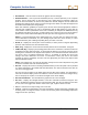
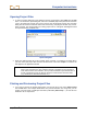
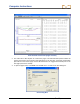
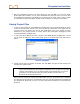
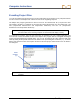
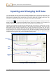
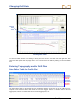
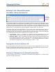
Table Of Contents
- Operator’s Manual
- Digital
- Control
- Incorporated
- Safety Precautions and Warnings
- Introduction
- System Components
- Startup and Operating Instructions
- SST Operating Procedure
- Setting Up SST Laptop
- Setting Up Equipment and Site
- 2. Establish Borepath Reference Line and Mark Borepath
- 3. Assemble and Torque-up Non-Magnetic Housing to Non-Mag Tool
- 4. Align Drill to Marked Borepath
- 5. Position & Align Non-mag Tooling Assembly onto Marked Borepath
- 6. Stage SST Equipment and Power Sources Adjacent to Tooling Assembly
- 7. Power Up Eclipse SST Equipment
- 8. Measure SST Transmitter Current Draw
- 9. Install SST Transmitter into Aligned Non-mag Tooling Assembly
- Setting Reference Heading (Ref Yaw) and Roll Offset
- Calibrating SST Tool and Confirming Proper System Operation
- Logging Drill Run
- Summary of Basic Operating Procedure
- SST Operating Procedure
- Computer Software Instructions
- Inputting and Changing Drill Data
- APPENDIXImporting Topography, Drill Plan, and Planned Deviation from Excel File
- LIMITED WARRANTY

Changing Drill Data
The Profile plot table lists the four plotted profiles—Tool Depth, Topography, Interpolated Topography,
and Drill Plan. The upper row for each of these plots gives the x-coordinate or horizontal distance from
the launch point. The lower row gives the y-coordinate, or the distance above or below the zero elevation
line or x-axis.
Tool Depth – These x,y coordinates are computer generated automatically by the SST system’s
software when you log the bore—you will not enter any information in these two rows.
Topography – These x,y coordinates are based off of the zero elevation
(launch point) and are manually entered either prior to, during, or after the bore. If the topography
is below the zero elevation line, you must enter a minus (“–”) sign; however, if the topo is above
the
zero elevation line you do not have to enter a plus (“+”) sign.
Interpolated Topography – These x,y coordinates are computer generated automatically by the
SST system’s software when you log the bore—you will not enter any information in these two
rows.
Drill Plan – These x,y coordinates are used for plotting a planned bore and are manually entered
either prior to, during, or after the bore. If the drill plan is entered after the topography has been
entered, the y-value will be based off of the topo . If no
topo is entered, the y-value will be based off of
the zero elevation line.
If you are using English units of measure for depth, the number must be in decimal format for feet; e.g., if
you want to use the value 4 ft 8 in., you will enter 4.
67. If you are using metric units of measure for depth,
then the number must be in decimal format for meters. The values for the x,y coordinates for the
Topography and Drill Plan will be based off of the zero elevation line, which is established at the first
logged point. If the Topography and/or Drill Plan is below the zero elevation line, then you must enter a
“–” sign. If the Topography and/or Drill Plan is above the zero elevation line, you do not have to enter a
“+” sign.
Entering or Changing Topography and Drill Plan Data
in Profile Table
The first column for the Tool Depth plot will always show as x = 0.00 and y = 0.00, because the first point
recorded on an SST bore is when the tool is ½ in the ground and ½ out of the
ground—referred to as the
zero, zero point. When manually entering the Drill Pan, you must enter for the coordinates in the first
column 0.00, 0.00. The first column for the topography data does not require this.
You do not need to enter x,y coordinates for every logged location. For instance if you only have five topo
points to plot, you will only have five columns of data with the first column corresponding to the shortest x-
distance and the last column having the largest x-distance.
To enter or change values for the x,y coordinates in the Topography or Drill Plan data, double-click on a
value and then type in the new value and hit enter.
Notice that when you display the toolbars and the Data Editor, the plots may appear compressed or
distort
ed. The plots should return to normal after the toolbars and Data Editor are closed.
Eclipse
®
SST
®
Operator’s Manual 49