
User Manual
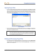
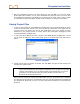
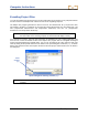
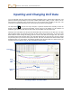
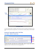
Table Of Contents
- Operator’s Manual
- Digital
- Control
- Incorporated
- Safety Precautions and Warnings
- Introduction
- System Components
- Startup and Operating Instructions
- SST Operating Procedure
- Setting Up SST Laptop
- Setting Up Equipment and Site
- 2. Establish Borepath Reference Line and Mark Borepath
- 3. Assemble and Torque-up Non-Magnetic Housing to Non-Mag Tool
- 4. Align Drill to Marked Borepath
- 5. Position & Align Non-mag Tooling Assembly onto Marked Borepath
- 6. Stage SST Equipment and Power Sources Adjacent to Tooling Assembly
- 7. Power Up Eclipse SST Equipment
- 8. Measure SST Transmitter Current Draw
- 9. Install SST Transmitter into Aligned Non-mag Tooling Assembly
- Setting Reference Heading (Ref Yaw) and Roll Offset
- Calibrating SST Tool and Confirming Proper System Operation
- Logging Drill Run
- Summary of Basic Operating Procedure
- SST Operating Procedure
- Computer Software Instructions
- Inputting and Changing Drill Data
- APPENDIXImporting Topography, Drill Plan, and Planned Deviation from Excel File
- LIMITED WARRANTY

Computer Instructions
¾ Recal Button – Used to redraw or refresh the graph if data has changed.
¾ Pullback Buttons – Used to pull rods backward (retreat) or forward (advance) in the computer
program. The left arrow button is used when the tool is pulled back for redirection. When you
press the left arrow button, the data for the pulled back rod will disappear and the Profile and
Deviation plots will get shorter. When you press the right arrow button, the data will reappear and
the Profile and Deviation plots will get longer.
When tool redirection (pullback) is required, press the left arrow until the appropriate number of
rods has been “pulled back”. Be sure to communicate with the drill operator to ensure that the
same number of rods is pulled back. As the bore is redrilled, you will press the LOG button to log
the redrilled rods. When you do this, you will no longer see or have access to the old rod data (or
portions of the Profile and Deviation plots) because you have now “logged over” the old data.
NOTE: It is recommended that, before pulling back rods, you save data as a different file name,
such as Bore1Rev1, Bore1Rev2, etc. (see “Saving Project Files” later in this section). It is also
recommended that, prior to drilling and pulling back, you make a rod count.
¾ PITCH, % – Displays the current pitch of the transmitter, in either percent or degrees (depending
upon the units selected in the Job Information field).
¾ ROLL, Deg – Displays the current roll and roll offset positions for the transmitter, in degrees.
¾ CURR YAW, Deg – Displays yaw (heading) information for the transmitter. This field contains two
checkboxes and two data input boxes. A check mark will appear in the top box, with the current
heading of the transmitter in the adjacent data input box. If it is determined that this information is
not correct, due to a localized interference source, it is possible to override the current yaw
setting to one that is believed to be correct. To override the current yaw, click on the second
checkbox (to enter a checkmark), and then enter the appropriate yaw value in the adjacent data
input box labeled Override.
NOTE: Yaw readings may vary with roll orientation. Always use the same roll position to log data
or click the checkbox next to the Override input box.
¾ Ref Yaw – Displays the reference heading established when you shot the probe. This is provided
as a quick comparison to the CURR YAW described above. The value is identical to the value for
Yaw, Ref in the logged data.
The Ref Yaw gets recorded on the laptop when the first data point is logged. The information is
sent from the remote display, where it is called the Yaw Ref. The Ref Yaw can be changed at any
time on the laptop as required; it can also be changed on the remote display.
¾ Ref Yaw Recal Button – This will redraw the graph if the Ref Yaw is changed.
¾ Dev Yaw – Displays the left/right deviation of the SST transmitter measured in degrees. This
value is the difference between the Ref Yaw and CURR YAW. The value is identical to the value
for Yaw, Dev in the logged data. Positive values to the right, negative values to the left.
¾ Volt, % – References the input voltage, 12V to 24V DC.
¾ Temp, F – Displays the temperature of the SST transmitter in degrees Fahrenheit, if English units
are being used, or in degrees Celsius, if metric units are being used. Normal drilling temperature
ranges are 60–82°F (16–28°C)
42 Eclipse
®
SST
®
Operator’s Manual