
User Manual

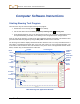
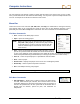
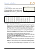
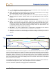
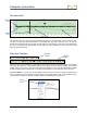
Table Of Contents
- Operator’s Manual
- Digital
- Control
- Incorporated
- Safety Precautions and Warnings
- Introduction
- System Components
- Startup and Operating Instructions
- SST Operating Procedure
- Setting Up SST Laptop
- Setting Up Equipment and Site
- 2. Establish Borepath Reference Line and Mark Borepath
- 3. Assemble and Torque-up Non-Magnetic Housing to Non-Mag Tool
- 4. Align Drill to Marked Borepath
- 5. Position & Align Non-mag Tooling Assembly onto Marked Borepath
- 6. Stage SST Equipment and Power Sources Adjacent to Tooling Assembly
- 7. Power Up Eclipse SST Equipment
- 8. Measure SST Transmitter Current Draw
- 9. Install SST Transmitter into Aligned Non-mag Tooling Assembly
- Setting Reference Heading (Ref Yaw) and Roll Offset
- Calibrating SST Tool and Confirming Proper System Operation
- Logging Drill Run
- Summary of Basic Operating Procedure
- SST Operating Procedure
- Computer Software Instructions
- Inputting and Changing Drill Data
- APPENDIXImporting Topography, Drill Plan, and Planned Deviation from Excel File
- LIMITED WARRANTY
DIGITAL CONTROL INCORPORATED
Computer Software Instructions
Starting Steering Tool Program
There are three ways to start the Eclipse Steering Tool program:
¾ Double-click on the Steering Tool icon
on the desktop.
¾ Use the Start button and select Start | Programs | Steering Tool |
Steering Tool.
¾ From Windows Explorer, click on the SteeringTool.exe file in the C:\Program Files\Digital Control
Incorporated\Steering Tool folder, or the folder you have designated for the storage location.
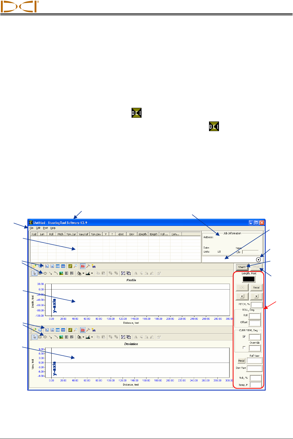
After you start up the program, you will see the main application window (see below). This window is also
generated from within the program by using the File | New command on the menu bar.
The Steering Tool software displays detailed information about the bore in a rod-by-rod tabular format. It
also shows a two-dimensional Profile plot of the bore and a bird’s-eye view of left/right deviation. The
main features and information areas are identified on the picture of the main application window shown
below, and then they are described in this subsection.
Title Ba
r
Job Information
Main Steering Tool Application Window
Menu
Bar
Logged
Data
COM Port
Status
Window
Deviation
Plot
Profile
Plot
x-axis
Status Ball
(flashes)
ST
A
RT
Button
Live
Data
STOP
Button
Profile
Plot
Toolbars
Deviation
Plot
Toolbars
x-axis
Eclipse
®
SST
®
Operator’s Manual 33