
User Manual
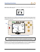
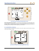
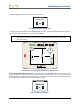
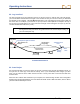
Table Of Contents
- Operator’s Manual
- Digital
- Control
- Incorporated
- Safety Precautions and Warnings
- Introduction
- System Components
- Startup and Operating Instructions
- SST Operating Procedure
- Setting Up SST Laptop
- Setting Up Equipment and Site
- 2. Establish Borepath Reference Line and Mark Borepath
- 3. Assemble and Torque-up Non-Magnetic Housing to Non-Mag Tool
- 4. Align Drill to Marked Borepath
- 5. Position & Align Non-mag Tooling Assembly onto Marked Borepath
- 6. Stage SST Equipment and Power Sources Adjacent to Tooling Assembly
- 7. Power Up Eclipse SST Equipment
- 8. Measure SST Transmitter Current Draw
- 9. Install SST Transmitter into Aligned Non-mag Tooling Assembly
- Setting Reference Heading (Ref Yaw) and Roll Offset
- Calibrating SST Tool and Confirming Proper System Operation
- Logging Drill Run
- Summary of Basic Operating Procedure
- SST Operating Procedure
- Computer Software Instructions
- Inputting and Changing Drill Data
- APPENDIXImporting Topography, Drill Plan, and Planned Deviation from Excel File
- LIMITED WARRANTY

Operating Instructions
26 Eclipse
®
SST
®
Operator’s Manual
Calibrating SST Tool and Confirming Proper System Operation
13. Calibrate SST Tool to Receiver
In this step, you will use the receiver to conduct a high-frequency calibration, and then you will verify ac-
curate depth readings using a tape measure.
First, ensure that there are no metal structures within 30 ft (9 m), such as steel pipe, chain-link fence,
metal siding, construction equipment, or automobiles. Also make sure that the receiver is not positioned
over rebar or underground utilities. Check signal strength by selecting Steering from the main menu
screen. Position the receiver 10 ft (3 m) to the side of the SST transmitter, as shown in the figure.
10 ft (3 m)
Eclipse SST
Receiver
SST Transmitter
Centerline
SST
Transmitter
(Inside
Non-Mag
Housing)
10-Foot Measurement for Calibration Procedure
Verify that the signal strength at this distance is 580 to 590. Return to the main menu screen (toggle down
once). Select Configure on the main menu screen and click the trigger. Select 1 Pt. Cal. and follow the
prompts to complete a high-frequency calibration. Return to the steering screen, and check depth
readings at several locations against the tape measure.
14. Measure SST Transmitter Current Draw in Housing
Using an amp meter hooked up in series, as shown in the figure “Power Up SST Transmitter and Take
Amp Reading” in step 7, measure the current draw of the SST transmitter, a good reading is 0.2 to 0.5
amps.
15. Verify Pitch Readings Using Digital Level
Compare the SST transmitter’s pitch readings at the remote display and the receiver with those shown on
a digital level. Position the digital level on the housing, and then lift or lower the housing to different
inclinations and compare the readings on the level against the remote’s and the receiver’s pitch readings
to confirm accuracy.
16. Connect SST Equipment to the Drill
You are now ready to connect the SST transmitter’s 10-gauge wire to the monel’s 10-gauge wire with a
butt splice and heat shrink. The monel is a non-mag drill pipe that measures approximately 15 ft (3 m) in
length and must be used between the non-mag housing and the regular drill pipe. Once this wire con-
nection is made, the housing can be threaded onto the monel while carefully pulling the slack in the wire
to ensure that the wire does not get caught in the threads.