
User Manual
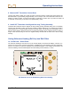
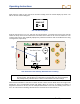
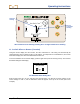
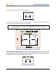
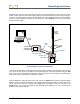
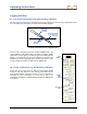
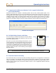
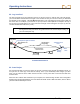
Table Of Contents
- Operator’s Manual
- Digital
- Control
- Incorporated
- Safety Precautions and Warnings
- Introduction
- System Components
- Startup and Operating Instructions
- SST Operating Procedure
- Setting Up SST Laptop
- Setting Up Equipment and Site
- 2. Establish Borepath Reference Line and Mark Borepath
- 3. Assemble and Torque-up Non-Magnetic Housing to Non-Mag Tool
- 4. Align Drill to Marked Borepath
- 5. Position & Align Non-mag Tooling Assembly onto Marked Borepath
- 6. Stage SST Equipment and Power Sources Adjacent to Tooling Assembly
- 7. Power Up Eclipse SST Equipment
- 8. Measure SST Transmitter Current Draw
- 9. Install SST Transmitter into Aligned Non-mag Tooling Assembly
- Setting Reference Heading (Ref Yaw) and Roll Offset
- Calibrating SST Tool and Confirming Proper System Operation
- Logging Drill Run
- Summary of Basic Operating Procedure
- SST Operating Procedure
- Computer Software Instructions
- Inputting and Changing Drill Data
- APPENDIXImporting Topography, Drill Plan, and Planned Deviation from Excel File
- LIMITED WARRANTY
Operating Instructions
Write down this value as your Yaw Ref or reference heading. Push the remote display’s up arrow. You
will see the Set Yaw Ref dialog box.
Set Yaw Ref Dialog Box
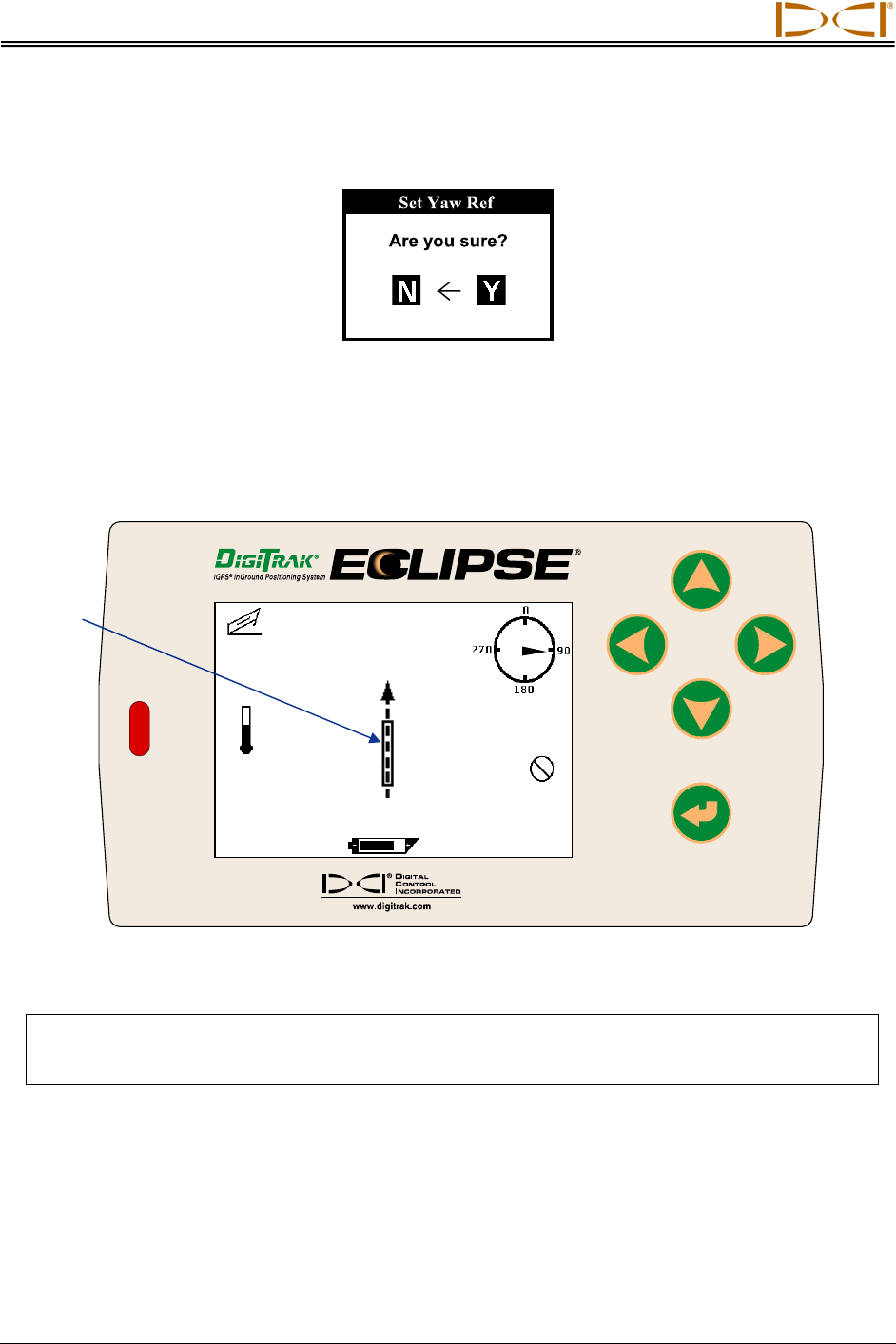
Push the right arrow to Y for Yes, and push the execute button. You should now see that the Yaw Ref
number at the top of the screen matches the Yaw number at the bottom of the screen as shown here. The
Yaw Ref and Yaw are also graphically displayed by a dashed vertical line with an arrowhead and a long
rectangular box, respectively.
7.5
%
75
o
F
Yaw Ref:170.0
o
Yaw:170.0
o
90°
Tool
Icon
SST Remote Screen Showing New Reference Heading
NOTE: If possible, take a Ref Yaw reading at a different location along the borepath, and/or at
the exit location. This will allow you to determine an average Ref Yaw over the borepath
and possibly identify variations in the Yaw that could result in inaccurate readings.
When the SST transmitter’s Yaw does not match the Ref Yaw the tool icon will be to the left or right of the
dashed line and a corresponding number will display above the tool icon to indicate the number of
degrees that the SST is off line, as in the example shown below. In this case, the heading of the SST is
60.7° off of the reference heading, which means the tool needs to be steered left 60.7°.
22 Eclipse
®
SST
®
Operator’s Manual