
User Manual
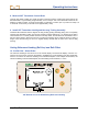
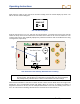
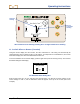
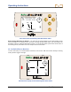
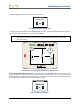
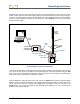
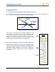
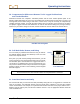
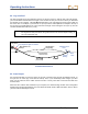
Table Of Contents
- Operator’s Manual
- Digital
- Control
- Incorporated
- Safety Precautions and Warnings
- Introduction
- System Components
- Startup and Operating Instructions
- SST Operating Procedure
- Setting Up SST Laptop
- Setting Up Equipment and Site
- 2. Establish Borepath Reference Line and Mark Borepath
- 3. Assemble and Torque-up Non-Magnetic Housing to Non-Mag Tool
- 4. Align Drill to Marked Borepath
- 5. Position & Align Non-mag Tooling Assembly onto Marked Borepath
- 6. Stage SST Equipment and Power Sources Adjacent to Tooling Assembly
- 7. Power Up Eclipse SST Equipment
- 8. Measure SST Transmitter Current Draw
- 9. Install SST Transmitter into Aligned Non-mag Tooling Assembly
- Setting Reference Heading (Ref Yaw) and Roll Offset
- Calibrating SST Tool and Confirming Proper System Operation
- Logging Drill Run
- Summary of Basic Operating Procedure
- SST Operating Procedure
- Computer Software Instructions
- Inputting and Changing Drill Data
- APPENDIXImporting Topography, Drill Plan, and Planned Deviation from Excel File
- LIMITED WARRANTY

Operating Instructions
8. Measure SST Transmitter Current Draw
Using an amp meter hooked up in series as shown in the figure above, measure the current draw of the
SST transmitter—a good reading is approximately 0.2 to 0.5 amps. The current draw will increase as the
distance you drill increases . A normal current draw, for
example, at 1500 ft (457 m) is about 0.7 amps. Th
e maximum current draw you should see is approxi-
mately 1 amp.
9. Install SST Transmitter into Aligned Non-mag Tooling Assembly
Install the SST transmitter into the aligned non-mag housing (tooling assembly) being sure to completely
seat the SST transmitter’s index slot onto the housing’s internal clocking key; you should not be able to
rotate the SST if it is correctly seated. Disconnect the amp meter, and reconnect the transmitter’s wire to
the DCI power
supply’s white wire. Be sure to ground the housing; this is commonly done by cutting a
length of wire and touching one end to a negative battery terminal and the other end to the non-mag
housing.
Setting Reference Heading (Ref Yaw) and Roll Offset
10. Set Ref Yaw – Shoot Probe
The reference heading or Ref Yaw is set on the remote display. The remote will display “Yaw Ref: 0.0°”
near the top of the screen, and near the bottom it will display the current heading of the SST transmitter,
which in our case is the reference heading of the intended borepath. In the example shown below, the
reference heading of the intended borepath, and the heading of the transmitter, is 170.0°.
90°
7.5
%
SST Remote Screen for Establishing Reference Heading
Eclipse
®
SST
®
Operator’s Manual 21