
User Manual
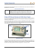
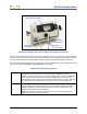

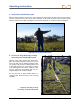
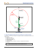
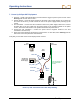
Table Of Contents
- Operator’s Manual
- Digital
- Control
- Incorporated
- Safety Precautions and Warnings
- Introduction
- System Components
- Startup and Operating Instructions
- SST Operating Procedure
- Setting Up SST Laptop
- Setting Up Equipment and Site
- 2. Establish Borepath Reference Line and Mark Borepath
- 3. Assemble and Torque-up Non-Magnetic Housing to Non-Mag Tool
- 4. Align Drill to Marked Borepath
- 5. Position & Align Non-mag Tooling Assembly onto Marked Borepath
- 6. Stage SST Equipment and Power Sources Adjacent to Tooling Assembly
- 7. Power Up Eclipse SST Equipment
- 8. Measure SST Transmitter Current Draw
- 9. Install SST Transmitter into Aligned Non-mag Tooling Assembly
- Setting Reference Heading (Ref Yaw) and Roll Offset
- Calibrating SST Tool and Confirming Proper System Operation
- Logging Drill Run
- Summary of Basic Operating Procedure
- SST Operating Procedure
- Computer Software Instructions
- Inputting and Changing Drill Data
- APPENDIXImporting Topography, Drill Plan, and Planned Deviation from Excel File
- LIMITED WARRANTY

Operating Instructions
MINIMUM
30-ft (9-m)
NO METAL ZONE
Drill
Centerline
of Boom
Centerpoint of
Drive Chuck
Transit
Non-mag Tooling
Assembly with
Bit Oriented at 0°
Surveyed and
Marked Borepath
At Least
30 ft (9 m)
from Tool
to Drill
About 10 ft (3 m)
from Transit
to Drill
SST Job Site Setup
6. Stage SST Equipment and Power Sources Adjacent to Tooling Assembly
In preparation for powering up the Eclipse SST equipment, position the following items adjacent to the
tooling assembly:
Eclipse SST receiver
Eclipse SST remote display
Eclipse SST transmitter
DCI NiCad battery for receiver
DCI power supply
Power source, such as a generator, 12V battery, or additional DCI NiCad battery
Amp meter
NOTE: Keep the remote display with its magnetic mounting bracket at least 5 ft (1.5 m) from
the SST transmitter or damage to the SST transmitter could occur.
Eclipse
®
SST
®
Operator’s Manual 19