
User Manual
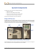
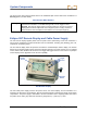
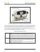
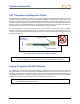

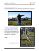
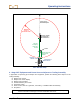
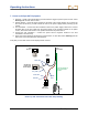
Table Of Contents
- Operator’s Manual
- Digital
- Control
- Incorporated
- Safety Precautions and Warnings
- Introduction
- System Components
- Startup and Operating Instructions
- SST Operating Procedure
- Setting Up SST Laptop
- Setting Up Equipment and Site
- 2. Establish Borepath Reference Line and Mark Borepath
- 3. Assemble and Torque-up Non-Magnetic Housing to Non-Mag Tool
- 4. Align Drill to Marked Borepath
- 5. Position & Align Non-mag Tooling Assembly onto Marked Borepath
- 6. Stage SST Equipment and Power Sources Adjacent to Tooling Assembly
- 7. Power Up Eclipse SST Equipment
- 8. Measure SST Transmitter Current Draw
- 9. Install SST Transmitter into Aligned Non-mag Tooling Assembly
- Setting Reference Heading (Ref Yaw) and Roll Offset
- Calibrating SST Tool and Confirming Proper System Operation
- Logging Drill Run
- Summary of Basic Operating Procedure
- SST Operating Procedure
- Computer Software Instructions
- Inputting and Changing Drill Data
- APPENDIXImporting Topography, Drill Plan, and Planned Deviation from Excel File
- LIMITED WARRANTY

D IGITAL C ONTROL INCORPORATED
Startup and Operating Instructions
The Eclipse SST system provides information at the remote display and the computer that enables you to
make accurate (reliable) steering decisions. It also logs and saves the drill data.
This section provides detailed operating instructions for using the system. Please read over the procedure
carefully and ensure that you understand all the instructions before you attempt to do it yourself.
Other components that you will need in addition to the SST system components are listed below. These
items are not provided by DCI with the SST system, but they are needed for setting up and operating the
system.
Non-magnetic housing and monel
Surveying equipment (transit or theodolite)
Stakes or string for marking reference line
Butt splices and heat shrinks for wireline connections or DCI CableLink-installed rods
10-gauge wire – approximately 20 ft (6 m) for use in establishing the reference heading
Tools for crimping
12V battery or power supply
Alligator clips and wire nuts to connect appropriate wires to power and ground sources
Tape measure
Digital level
Amp meter
SST Operating Procedure
Setting Up SST Laptop
1. Plotting Topography, Drill Plan, and Planned Deviation
Prior to drilling, you may want to input topographic and/or planned bore information into the SST software.
This information can be input during the drilling/logging process, although it is not recommended unless
you have a dedicated computer operator to ensure correct and accurate input. Instructions for manually
inputting this data are provided in detail later in this manual under the section titled Inputting and
Changing Drill Data.
Setting Up Equipment and Site
2. Establish Borepath Reference Line and Mark Borepath
DCI recommends that you use surveying equipment to establish the borepath. Once, established, mark
the borepath with a string line based off of the survey markers. This reference line will
help in aligning the drill and non-mag tooling assembly to the intended borepath.
3. Assemble and Torque-up Non-Magnetic Housing to Non-Mag Tool
Using the drill rig or other hydraulic torquing wrenches, thread the non-mag housing to the non-mag tool
and torque-up.
Eclipse
®
SST
®
Operator’s Manual 17