
User Manual
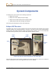

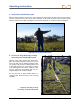
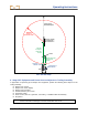
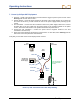
Table Of Contents
- Operator’s Manual
- Digital
- Control
- Incorporated
- Safety Precautions and Warnings
- Introduction
- System Components
- Startup and Operating Instructions
- SST Operating Procedure
- Setting Up SST Laptop
- Setting Up Equipment and Site
- 2. Establish Borepath Reference Line and Mark Borepath
- 3. Assemble and Torque-up Non-Magnetic Housing to Non-Mag Tool
- 4. Align Drill to Marked Borepath
- 5. Position & Align Non-mag Tooling Assembly onto Marked Borepath
- 6. Stage SST Equipment and Power Sources Adjacent to Tooling Assembly
- 7. Power Up Eclipse SST Equipment
- 8. Measure SST Transmitter Current Draw
- 9. Install SST Transmitter into Aligned Non-mag Tooling Assembly
- Setting Reference Heading (Ref Yaw) and Roll Offset
- Calibrating SST Tool and Confirming Proper System Operation
- Logging Drill Run
- Summary of Basic Operating Procedure
- SST Operating Procedure
- Computer Software Instructions
- Inputting and Changing Drill Data
- APPENDIXImporting Topography, Drill Plan, and Planned Deviation from Excel File
- LIMITED WARRANTY

System Components
Non-DCI Components That Will Be Needed
There are pieces of equipment, tooling, and some specialty items required for the operation of the SST
system that are not supplied by DCI. Below is a list of items needed for the operation of the SST system
and to make the wire connections:
Non-magnetic housing for SST transmitter
Monel (non-magnetic drill rod) approximately 15 ft (3 m) long for use between the non-mag
housing and the first drill rod. A second monel may be required if you are using a mud motor.
Fish tape or device to fish wire through rod
Approximately 20 ft (6 m) of 10-gauge wire
Butt splices for 10/12 gauge wire
Crimper
Heat shrinks
Heat gun
Transit or theodolite
String for string line
Tape measure
12V battery or power supply
Amp meter
Digital level
Eclipse
®
SST
®
Operator’s Manual 15