
User Manual
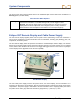
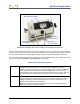
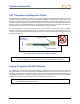

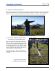
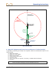
Table Of Contents
- Operator’s Manual
- Digital
- Control
- Incorporated
- Safety Precautions and Warnings
- Introduction
- System Components
- Startup and Operating Instructions
- SST Operating Procedure
- Setting Up SST Laptop
- Setting Up Equipment and Site
- 2. Establish Borepath Reference Line and Mark Borepath
- 3. Assemble and Torque-up Non-Magnetic Housing to Non-Mag Tool
- 4. Align Drill to Marked Borepath
- 5. Position & Align Non-mag Tooling Assembly onto Marked Borepath
- 6. Stage SST Equipment and Power Sources Adjacent to Tooling Assembly
- 7. Power Up Eclipse SST Equipment
- 8. Measure SST Transmitter Current Draw
- 9. Install SST Transmitter into Aligned Non-mag Tooling Assembly
- Setting Reference Heading (Ref Yaw) and Roll Offset
- Calibrating SST Tool and Confirming Proper System Operation
- Logging Drill Run
- Summary of Basic Operating Procedure
- SST Operating Procedure
- Computer Software Instructions
- Inputting and Changing Drill Data
- APPENDIXImporting Topography, Drill Plan, and Planned Deviation from Excel File
- LIMITED WARRANTY
System Components
SST Transmitter and Magnetic Shield
The Eclipse SST transmitter is similar to the standard Eclipse cable transmitter except that it also
provides heading or yaw information. This information, in addition to the pitch and roll data, enables the
drill operator to determine the SST transmitter’s position and heading, and thus allows steering of the tool.
The SST transmitter provides yaw and pitch updates every 1.3 seconds and roll updates more than 3
times per second. The SST transmitter has a changeable tail wire assembly; two spare assemblies are
provided with the SST transmitter so that the assembly can be rebuilt as needed.
The SST transmitter is a magnetic-sensitive device, and it needs to be kept away from all magnetic
sources. A protective magnetic shield, which is essentially a copper sleeve, is provided with the SST
transmitter. The magnetic shield should be placed on the end of the SST transmitter at all times when the
transmitter is not in use.
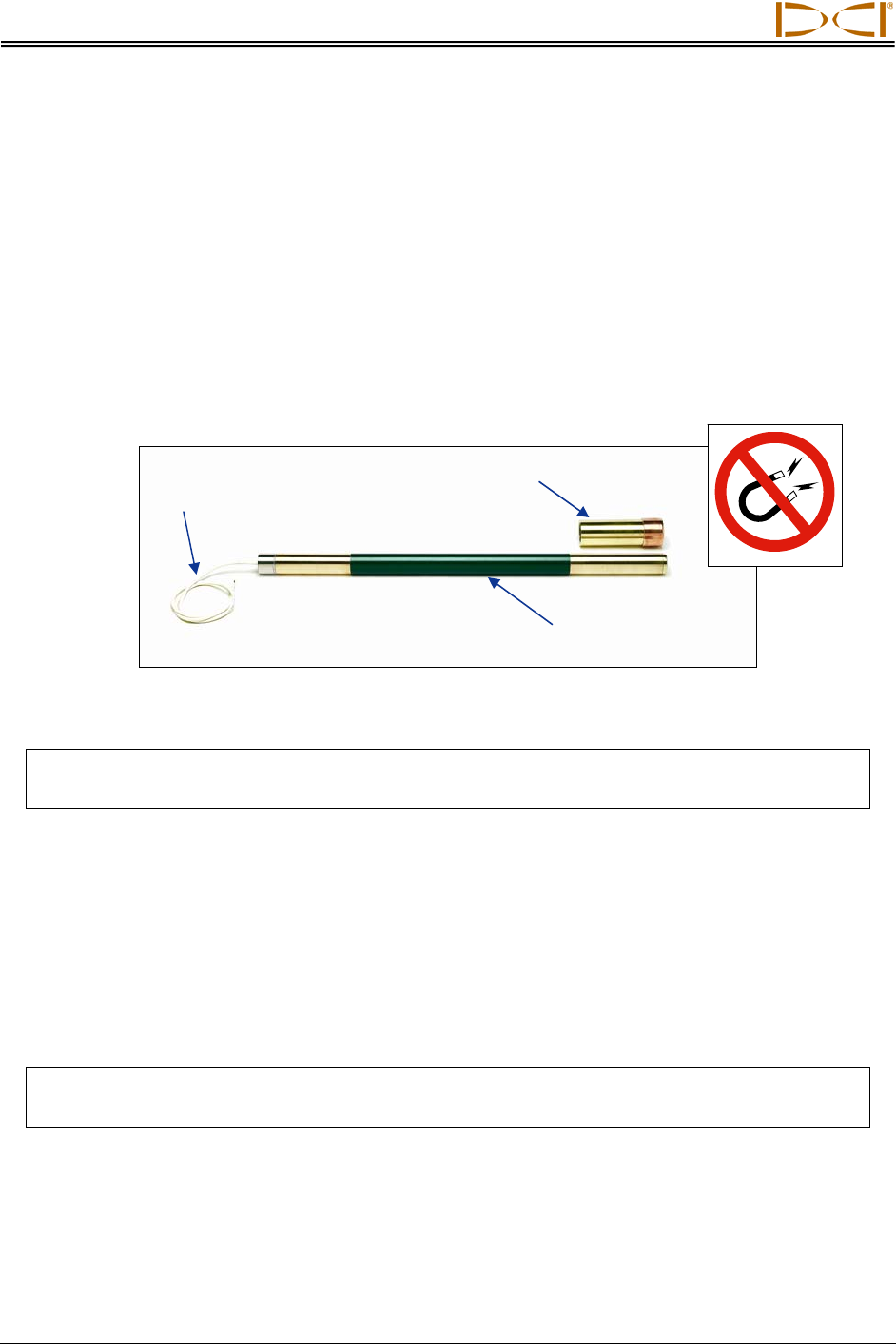
Magnetic Shield
White Wire to
Power Supply
SST Transmitte
r
SST Transmitter and Protective Magnetic Shield
NOTE: The SST transmitter must be kept at least 5 ft (1.5 m) away from all magnets including
the remote display, which has a magnetic mount that will damage the transmitter.
Laptop Computer with SST Software
The Eclipse SST system comes with a dedicated laptop computer (PC) that has the Steering Tool soft-
ware preinstalled. A USB-to-serial adapter is provided along with a 50-ft (15-m) long serial cable for
connecting the computer to the remote display. A CD that contains both the Steering Tool software and
this operator’s manual (in a PDF file) is also provided with the system. See the next section (Computer
Software Instructions) for more information about the software and how to use it.
NOTE: Loading additional programs on the dedicated SST laptop could cause problems with
the functioning of the SST software.
14 Eclipse
®
SST
®
Operator’s Manual