
User Manual
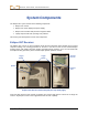
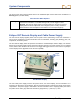
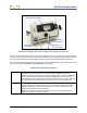
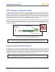

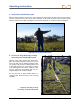
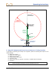
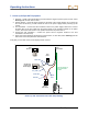
Table Of Contents
- Operator’s Manual
- Digital
- Control
- Incorporated
- Safety Precautions and Warnings
- Introduction
- System Components
- Startup and Operating Instructions
- SST Operating Procedure
- Setting Up SST Laptop
- Setting Up Equipment and Site
- 2. Establish Borepath Reference Line and Mark Borepath
- 3. Assemble and Torque-up Non-Magnetic Housing to Non-Mag Tool
- 4. Align Drill to Marked Borepath
- 5. Position & Align Non-mag Tooling Assembly onto Marked Borepath
- 6. Stage SST Equipment and Power Sources Adjacent to Tooling Assembly
- 7. Power Up Eclipse SST Equipment
- 8. Measure SST Transmitter Current Draw
- 9. Install SST Transmitter into Aligned Non-mag Tooling Assembly
- Setting Reference Heading (Ref Yaw) and Roll Offset
- Calibrating SST Tool and Confirming Proper System Operation
- Logging Drill Run
- Summary of Basic Operating Procedure
- SST Operating Procedure
- Computer Software Instructions
- Inputting and Changing Drill Data
- APPENDIXImporting Topography, Drill Plan, and Planned Deviation from Excel File
- LIMITED WARRANTY

System Components
The SST receiver menu options include those in the standard Eclipse receiver main menu in addition to a
Steering option (see table below).
SST Receiver Menu Options
Steering
Puts the receiver into SST steering mode. This mode must be enabled to walkover
track the SST transmitter. To enable steering mode, use the toggle to select
Steering, then click the trigger. When in steering mode, the clock on the receiver
display (which indicates roll) shows units in degrees (from 0 to 360), whereas in
locate mode the units correspond to the numbers on a clock (1 through 12).
Eclipse SST Remote Display and Cable Power Supply
The SST remote display supplies power from the power source (drill battery) to the SST transmitter. It
also receives and displays real-time information from the transmitter, including yaw (heading), pitch, roll,
temperature, and battery status.
The SST remote display looks and operates much like the standard Eclipse remote display. The function
buttons on the keypad (toggle arrows and execute button) operate in the same manner as on a standard
remote, which is also similar to the functions of the toggle and trigger buttons on the receiver. Any Eclipse
remote display can be upgraded to have the SST capability.
Display
Screen
Toggle
Arrows
Execute
Button
SST Remote Display
The SST cable power supply connects the power source, the remote display, and the transmitter. It is
inserted in the back of the remote display, with the exposed terminals contacting the springs in the battery
compartment. The power supply is hard wired to the SST transmitter with a 10-gauge (white) wire and to
the power source with a gray cable that contains 14-gauge black (“–”) and red (“+”) wires.
12 Eclipse
®
SST
®
Operator’s Manual