® SST Guidance System ® Operator’s Manual DIGITAL CONTROL INCORPORATED DCI Headquarters DCI Europe DCI India DCI China DCI Australia 19625 62nd Ave. S., Suite B-103 Kent, Washington 98032 USA Tel 425 251 0559 / 800 288 3610 Fax 253 395 2800 E-mail DCI@digital-control.com Kurmainzer Strasse 56 D-97836 Bischbrunn Germany Tel +49(0) 9394 990 990 Fax +49(0) 9394 990 999 DCI.Europe@digital-control.
DIGITAL CONTROL INCORPORATED 3-1200-00-D © 2003-2008 by Digital Control Incorporated. All rights reserved. February 2008 edition. Trademarks The DCI logo, CableLink®, DataLog®, DigiTrak®, Eclipse®, iGPS®, Intuitive®, look-ahead®, SST®, target-inthe-box®, Target Steering®, and TensiTrak® are U.S. registered trademarks, and DucTrak™, FasTrak™, LT™, SuperCell™, and TeleLock™ are trademarks of Digital Control Incorporated.
DIGITAL CONTROL INCORPORATED Table of Contents SAFETY PRECAUTIONS AND WARNINGS................................................................................................ 5 INTRODUCTION........................................................................................................................................... 7 SYSTEM COMPONENTS........................................................................................................................... 11 Eclipse SST Receiver................
DIGITAL CONTROL INCORPORATED Table of Contents (Cont.) COMPUTER SOFTWARE INSTRUCTIONS .............................................................................................. 33 Starting Steering Tool Program ............................................................................................................ 33 Menu Bar........................................................................................................................................ 34 File Menu Commands .................
DIGITAL CONTROL INCORPORATED Safety Precautions and Warnings Important Note: All operators must read and understand the following Safety Precautions and Warnings and must review this DigiTrak® Eclipse® SST® Guidance System Operator’s Manual as well as the DigiTrak® Eclipse® inGround Positioning System Operator’s Manual before using this system.
DIGITAL CONTROL INCORPORATED Safety Precautions and Warnings (Cont.) ¾ Prior to the start of each drilling run, test the DigiTrak Eclipse SST system to confirm that it is operating properly and check that it is providing accurate drill head location and heading information and accurate drill head depth, pitch, and roll information with the transmitter inside the drill head.
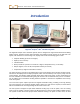
DIGITAL CONTROL INCORPORATED Introduction DigiTrak® Eclipse® SST® Guidance System The DigiTrak® Eclipse® SST® Guidance System, which is designed for tough horizontal directional drilling (HDD) projects, provides real-time tool information that enables accurate steering of the drill head.
Introduction transmitter and special non-magnetic housing are put aside, and the battery-operated Eclipse transmitter is used with a standard housing. A standard Eclipse system can be upgraded to the Eclipse SST system. Whether running the Eclipse SST transmitter or the battery-operated Eclipse transmitter, the target-in-thebox® locating feature and look-ahead® capability enable Intuitive® tracking of the transmitter.
Introduction for the Eclipse locating system (DigiTrak® Eclipse® inGround Positioning System Operator’s Manual) before you try using the SST system. NOTE: You must know how to operate the Eclipse locating system prior to operating the Eclipse SST guidance system. DCI also recommends that you read the instructions given in this SST system operator’s manual and familiarize yourself with the various menu screens on your Eclipse SST receiver and remote display before using the system for a production drill.
Introduction Notes 10 Eclipse® SST® Operator’s Manual
DIGITAL CONTROL INCORPORATED System Components The Eclipse SST system consists of the following components: ¾ Eclipse SST receiver ¾ Eclipse SST remote display with power supply ¾ Eclipse SST transmitter with protective magnetic shield ¾ Laptop computer with SST (Steering Tool) software This section gives descriptions of these main components. Eclipse SST Receiver The Eclipse SST receiver is used to walkover locate the SST transmitter when possible and to confirm computer readings.
System Components The SST receiver menu options include those in the standard Eclipse receiver main menu in addition to a Steering option (see table below). SST Receiver Menu Options Steering Puts the receiver into SST steering mode. This mode must be enabled to walkover track the SST transmitter. To enable steering mode, use the toggle to select Steering, then click the trigger.
System Components SST Cable Power Supply Gray Cable to Power Source Serial Cable to Computer White Wire to SST Transmitter SST Remote Display with Power Supply and Computer Connection The SST remote display is connected to a laptop computer by means of a serial port. When connected, real-time data can be viewed at the computer, and data points can be logged by the computer operator. The SST software allows for viewing, logging, editing, graphing, saving, and printing of the drill data.
System Components SST Transmitter and Magnetic Shield The Eclipse SST transmitter is similar to the standard Eclipse cable transmitter except that it also provides heading or yaw information. This information, in addition to the pitch and roll data, enables the drill operator to determine the SST transmitter’s position and heading, and thus allows steering of the tool. The SST transmitter provides yaw and pitch updates every 1.3 seconds and roll updates more than 3 times per second.
System Components Non-DCI Components That Will Be Needed There are pieces of equipment, tooling, and some specialty items required for the operation of the SST system that are not supplied by DCI. Below is a list of items needed for the operation of the SST system and to make the wire connections: Non-magnetic housing for SST transmitter Monel (non-magnetic drill rod) approximately 15 ft (3 m) long for use between the non-mag housing and the first drill rod.
System Components Notes 16 Eclipse® SST® Operator’s Manual
D IGITAL C ONTROL INCORPORATED Startup and Operating Instructions The Eclipse SST system provides information at the remote display and the computer that enables you to make accurate (reliable) steering decisions. It also logs and saves the drill data. This section provides detailed operating instructions for using the system. Please read over the procedure carefully and ensure that you understand all the instructions before you attempt to do it yourself.
Operating Instructions 4. Align Drill to Marked Borepath With the transit positioned at least 10 ft (3 m) ahead of the drill, position the drill so that the transit sights onto the center point of the drive chuck and/or centerline of the boom. Anchor the drill, and then use the transit to confirm that the drill is still aligned to the marked borepath; if not, adjust for proper alignment. Aligning Drill to Marked Borepath 5.
Operating Instructions Surveyed and Marked Borepath MINIMUM 30-ft (9-m) NO METAL ZONE Non-mag Tooling Assembly with Bit Oriented at 0° At Least 30 ft (9 m) from Tool to Drill Transit About 10 ft (3 m) from Transit to Drill Centerline of Boom Centerpoint of Drive Chuck Drill SST Job Site Setup 6.
Operating Instructions 7. Power Up Eclipse SST Equipment 1. Receiver – Install a DCI NiCad battery pack and click the trigger to power up the receiver. Select Steering from the main menu screen. 2. Remote display – Insert DCI power supply into the back of the remote display. Do not power up the remote at this time; you will connect the SST to the power supply before powering up the remote. 3. SST transmitter – Connect the SST transmitter’s wire to the power supply’s white wire.
Operating Instructions 8. Measure SST Transmitter Current Draw Using an amp meter hooked up in series as shown in the figure above, measure the current draw of the SST transmitter—a good reading is approximately 0.2 to 0.5 amps. The current draw will increase as the distance you drill increases. A normal current draw, for example, at 1500 ft (457 m) is about 0.7 amps. Th e maximum current draw you should see is approxi-mately 1 amp. 9.
Operating Instructions Write down this value as your Yaw Ref or reference heading. Push the remote display’s up arrow. You will see the Set Yaw Ref dialog box. Set Yaw Ref Dialog Box Push the right arrow to Y for Yes, and push the execute button. You should now see that the Yaw Ref number at the top of the screen matches the Yaw number at the bottom of the screen as shown here.
Operating Instructions Reference Heading 7.5% Yaw Ref :170.0 o 60.7 o 90° Current Transmitter Heading 75 o F Yaw:230.7o SST Remote Screen Showing Heading 60.7° to Right of Reference Heading 11. Set Roll Offset on Remote (if needed) Using the remote display and the receiver, the SST transmitter’s 0° roll setting can electronically be compensated if it does not match the bit’s 0° roll position.
Operating Instructions -0.2% Roll Offset: 240° Yaw Ref : 170.0° 0.4° 0° 68 o F Yaw: 169.6° SST Remote Screen Showing New Roll Offset Value End or Change Roll Offset on Remote – You have now set the Roll Offset on the remote display. At the end of the drill run, or during the run if you want to change the Roll Offset value, you must remove the Roll Offset value by ending the Roll Offset function.
Operating Instructions Push the toggle right to Y for Yes to set the new roll offset. Set New Roll Offset Are you sure? Set New Roll Offset Dialog Box You will see the clock position on the display change to read 0°, and the Roll Offset value will appear at the top of the screen, as shown on the next receiver display.
Operating Instructions Calibrating SST Tool and Confirming Proper System Operation 13. Calibrate SST Tool to Receiver In this step, you will use the receiver to conduct a high-frequency calibration, and then you will verify accurate depth readings using a tape measure. First, ensure that there are no metal structures within 30 ft (9 m), such as steel pipe, chain-link fence, metal siding, construction equipment, or automobiles.
Operating Instructions Depending upon how the SST transmitter’s wire exits the drill pipe (through the drive chuck or the mud swivel), connect this wire to the power supply’s white wire (see figure below). Connect the power supply’s red wire to the positive battery terminal and the black wire to the negative terminal of the drill’s battery. Power the remote display by pressing the execute button, select Steering from the main screen and press the execute button.
Operating Instructions Logging Drill Run 17. Log First Point and Override Yaw Reading, If Needed The first logged point should be recorded when the SST transmitter (in the housing) is positioned so that it is ½ in and ½ out of the ground, as shown in the following diagram. Drill Head Entering Ground Surface of Ground or Zero Reference Elevation Slots in Housing Tooling Position for First Logged Point Once the tool is in position, press the computer’s LOG button.
Operating Instructions 19. Compensate for Differences Between Tool’s Logged Position Data and Tracked Position Differences between the computer’s calculated position and the tool’s tracked position (DEV in the laptop’s Logged Data field) can occur if the first reading was not taken when the SST was ½ in and ½ out of the ground, such as when using a mud motor. In such cases, it may be necessary to compensate by changing the pitch reading.
Operating Instructions 22. Log Last Rod The last rod logged is just as important as the first. At the end of the run, with the tool at the exit location, you must measure and document the length of the Last Rod so that you can enter it when you download the drill data to the computer. The Last Rod measurement is the rod length minus the length of drill rod left on the rack. For example, if you measure 6 ft (1.8 m) from the make-up/break-out clamps to the top of the rod, then you would subtract 6 ft (1.
Operating Instructions Summary of Basic Operating Procedure ¾ Setting Up SST Laptop 1. Establish borepath reference line and mark borepath. ¾ Setting Up Equipment and Site 2. Establish borepath reference line and mark borepath. 3. Assemble and torque up non-magnetic housing to non-mag tool. 4. Align drill to marked borepath. 5. Position and align non-mag tooling assembly onto marked borepath. 6. Stage SST equipment and power sources adjacent to tooling assembly. 7. Power up Eclipse SST equipment. 8.
Operating Instructions Notes 32 Eclipse® SST® Operator’s Manual
DIGITAL CONTROL INCORPORATED Computer Software Instructions Starting Steering Tool Program There are three ways to start the Eclipse Steering Tool program: ¾ Double-click on the Steering Tool icon ¾ Use the Start button and select Start | Programs | Steering Tool | ¾ From Windows Explorer, click on the SteeringTool.exe file in the C:\Program Files\Digital Control Incorporated\Steering Tool folder, or the folder you have designated for the storage location. on the desktop. Steering Tool.
Computer Instructions The SST Steering Tool software contains a sample data file (Demo V2.6.std) that you can use to familiarize yourself with what the data looks like while drilling. You may want to open the sample data file and use it for an example as we discuss the software in this section. Menu Bar Under each menu on the menu bar (File, Edit, Port, and Help) are commands for running the Steering Tool program. Many of the commands are similar to those used in other Windows programs.
Computer Instructions Specify Measurement Units Here Drill Information Dialog Box ¾ Chart Autoscaling – Allows you to keep the entire Profile and Deviation points viewable during the logging of a run. If Chart Autoscaling is not checked, then the Profile and Deviation plots will go “off the chart,” or outside the viewable area. This feature may be useful if a run is very long. Port Menu Commands The Port menu has four options, which are listed as 1, 2, 3, and 4.
Computer Instructions Job Information The Job Information field contains information about the project/bore including the address, date, time, pitch units (degrees or percent slope), and depth units (metric or feet). The information is entered in this field by clicking on Edit | Drill Information, and then clicking the checkboxes in the right column of the Drill Information dialog box to indicate your choices for units.
Computer Instructions T – The temperature of the SST transmitter in degrees Fahrenheit, when using English units (feet), or in degrees Celsius, when using metric units. xDist – The transmitter’s horizontal distance from the launch point. Note that this is not the length of the actual borehole. This value is measured along the x-axis. Dev – The transmitter’s lateral (left/right) distance from the borepath’s reference heading, displayed in either feet or meters.
Computer Instructions Deviation Plot Start of Bore OnBar lines Cursor Coordinates Borepath The Deviation plot area shows the lateral (left/right) deviation of the transmitter from the reference line. The plot is at the same horizontal position as the Profile plot, but from a bird’s-eye view. As with the Profile plot, this window has an automatic scaling feature to keep the plot “on the chart.
Computer Instructions Standard Toolbar The icons available on the standard toolbar are briefly described below. For details on how to use them, see “Graphing Options” in the Inputting and Changing Drill Data section. Import Topography Enables the import of topographic data from an Excel file. Copy to Clipboard Vertical Grid Copies data as a bitmap, metafile, or text file to the clipboard to save in another format. Displays vertical grid lines on the graph.
Computer Instructions Annotate Toolbar The icons available on the annotate toolbar are briefly described below. These icons enable functions similar to those provided in standard drawing applications. For details on how to use them, see “Graphing Options” in the Inputting and Changing Drill Data section. Pointer 40 Rectangle Allows cursor to be used as a selection tool and shows OnBar and coordinates for cursor point when left mouse button is clicked.
Computer Instructions Status Ball Open Port COM Port Status Window and START/STOP Buttons The COM Port Status Window indicates whether a COM (serial) port is open and connecting the computer to the SST transmitter through the remote display. The Status Ball on the right flashes when the computer is receiving data from the SST transmitter. The START and STOP buttons are used for opening and closing a port. Close Port A COM port must be open before bore data can be logged.
Computer Instructions ¾ Recal Button – Used to redraw or refresh the graph if data has changed. ¾ Pullback Buttons – Used to pull rods backward (retreat) or forward (advance) in the computer program. The left arrow button is used when the tool is pulled back for redirection. When you press the left arrow button, the data for the pulled back rod will disappear and the Profile and Deviation plots will get shorter.
Computer Instructions Opening Project Files 1. To open an existing drill project from within the Steering Tool program, select Open from the File menu. You will see the Open dialog box and a list of available project files (with the file extension “std”) in the folder that was last used. If this is the first time the program is being used, the Open dialog box will show the Drill Data folder under the Steering Tool program file with only one file, Demo V2.6.std.
Computer Instructions Print Preview of Drill Data (Pages 2 and 3) 2. The entire bore’s data will print on at least three pages. The drill information (which includes the job site and customer and contractor data) will appear on the first page, the Profile and Deviation plots will be on the second page, and the drill data listed in the Logged Data field will print on the third page (and more if needed). 3. To print the project data, select Print from the File menu. You will see the Print dialog box.
Computer Instructions 4. Make any adjustments needed in the Print dialog box, then click OK. If you have the Adobe Acrobat PDF writer software, you can select the Adobe PDF printer to print to a PDF file (see your software documentation). This allows you to save the file as a PDF, which can be e-mailed to and viewed by anyone with Adobe Acrobat reader (available at no charge on the Internet). Saving Project Files 1. To save an open project file, select Save from the File menu.
Computer Instructions E-mailing Project Files You can send Eclipse SST project files via e-mail. E-mailed files can be opened on any computer that has the same version of the Eclipse SST software as used on the originating computer. The Eclipse SST program generates five files for each run: the standard SST file (*.std) and four other files related to the plots. For example, for the project file named “Projectname.std”, there will be two *.chd files (“Projectname PlanView.chd” and “Projectname Profile.
DIGITAL CONTROL INCORPORATED Inputting and Changing Drill Data You can manually edit SST project files by plotting topography (topo), planned bore (drill plan), and planned deviation (tool deviation) into the SST software either before, during, or after a bore. You can also import this information from an Excel file, but it must be done prior to logging a SST bore. The instructions for importing information from an Excel file are provided in the Appendix.
Changing Drill Data Floating Data Table Floating Data Table To close the table, whether it is floating or fixed, place the cursor in the table area and right click, then select the Hide option from the popup menu. You can also close the table by clicking on the Data Editor icon.
Changing Drill Data The Profile plot table lists the four plotted profiles—Tool Depth, Topography, Interpolated Topography, and Drill Plan. The upper row for each of these plots gives the x-coordinate or horizontal distance from the launch point. The lower row gives the y-coordinate, or the distance above or below the zero elevation line or x-axis.
Changing Drill Data Entering Tool’s Planned Deviation Data Editor Table for Deviation Plot } Computer Generated } Manually Entered The Data Editor table for the Deviation plot has numbered columns across the top of the table that correspond to the locations where data will be or has been logged, as in the table for the Profile plot. Column 1 contains data for the first logged point; column 2 contains data for the second logged point, etc. Note that the first column will always have 0.
Changing Drill Data Graphing Options You can change the appearance of the Profile and Deviation plots in a variety of ways. The various options that are available are discussed below. Some options will alter the appearance of both plots, and some will only alter the plot in which you are working. Place your cursor in the plot area that you want to change to open the Chart FX dialog box that affects that plot area.
Changing Drill Data X Axis Properties Dialog Box – Scale Tab The Scale tab is automatically selected. Make the desired changes in the Minimum and Maximum boxes, and click Apply. You will see the plots adjust accordingly. Click on OK or on the “X” in the upper right corner of the Chart FX Properties dialog box to close it. NOTE: The X Axis properties affect both the Profile and Deviation plots. The Y Axis Properties affect only one plot.
Changing Drill Data Change Horizontal Scale (Move Y-Axis to Left or Right in Profile Plot) 1. 2. 3. 4. 5. 6. Right mouse click in Profile plot area. Select Properties... from popup menu. Click on Axes tab in Chart FX Properties dialog box. Click on drop-down arrow in upper left field and select X Axis. Click on Details button to open X Axis Properties dialog box.
Changing Drill Data In the graphic above, the Series tab is selected and the drop-down list for the top left field is clicked to display the four plots. Once one plot is selected, as shown below, the color, size, and shape of the line and data points for that plot can be changed. After making changes, click the Apply button to see the desired changes take effect.
Changing Drill Data Annotation Object Properties Dialog Box The next four icons after the cursor allow you to draw rectangles , circles or ovals , lines with or , and curved (arc) lines . These tools work in a similar manner to those without arrowheads provided in drawing programs. To use them, click on the icon and then place the cursor where you want to draw the item; click and hold in the mouse button as you drag the cursor to make the object the desired size.
Changing Drill Data Notes 56 Eclipse® SST® Operator’s Manual
DIGITAL CONTROL INCORPORATED APPENDIX Importing Topography, Drill Plan, and Planned Deviation from Excel File The SST software allows you to import topography, drill plan, and planned deviation data from a text file created in Microsoft Excel. This should be done before you start logging your SST bore. Create Text File The file must be in the correct format for importing, as shown in the following figure.
Appendix The first row of data will always consist of zeroes. This is because the first logged point is recorded when the SST transmitter (in the housing) is positioned so that it is ½ in and ½ out of the ground. This point is measured as zero, or 0.0, for both the x- and y-coordinates. Note that the x,y coordinate values must be in decimal format (not using fractions). For example, if you want to enter 4 ft 8 in., then you will enter the value 4.67.
Appendix 3. Type in the desired file name where indicated at the bottom of the dialog box. 4. Then select the “Text (Tab delimited) (*.txt)” option in the “Save as type” drop-down box at the bottom of the dialog box. 5. Click on Save. You will see the following dialog box: 6. Click OK. You will then see another dialog box appear as follows: 7. Click on Yes. The file has now been saved. In this example the file name is Test data.txt. You can now exit the Excel application.
Appendix 3. Select the file, after navigating to the folder where you saved it if necessary. 4. Click the Open button. You should see the three plotted profiles in the plot area of the SST application. Import of Text File 5. You may need to adjust the scaling. For example, the plots in the graphic above are compressed to the left of the plot area. See “Graphing Options” in the Inputting and Changing Drill Data section of the manual for information on how to edit the plots.
Appendix Appearance of Plots After Making Graphic Changes 6. You should save the data after it is in the desired format. To save, select the File | Save menu command to open the Save As dialog box. Save As Dialog Box in SST Application You have now saved the data as a Steering Tool file.
Appendix Notes 3-1200-00-D 62 Eclipse® SST® Operator’s Manual
DIGITAL CONTROL INCORPORATED 19625 62nd Ave. S., Suite B-103 y Kent, WA 98032 USA y (425) 251-0559 OR (800) 288-3610 y FAX (253) 395-2800 www.digitrak.com (Web Site) dci@digital-control.
DCI reserves the right to make changes in design and improvements upon DCI Products from time to time, and User understands that DCI shall have no obligation to upgrade any previously manufactured DCI Product to include any such changes.