
User's Manual
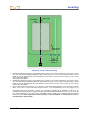
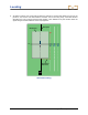
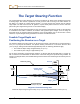
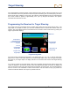
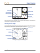

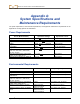
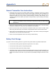
Table Of Contents
- Safety Precautions and Warnings
- Dear Customer:
- Introduction
- Receiver
- General Description
- Toggle and Trigger Switches
- Audible Tones
- Installing and Removing the Battery Pack
- Power On
- Power Off
- Main Menu
- Locate Mode
- Calibration Menu
- Height-Above-Ground (HAG) Menu
- Settings Menu
- Transmitter Selection Menu
- Drill DataLog Menu
- Pressure-Tension DataLog Menu
- Using the Keypad
- Display Screens
- Standard Receiver Display Screen Symbols
- Transmitter
- Remote Display
- Battery Charger
- System Setup
- Locating
- The Target Steering Function
- Appendix A: System Specifications and Maintenance Requirements
- Appendix B: Projected Depth Versus Actual Depth and the Fore/Aft Offset
- Appendix C: Calculating Depth Based on Distance Between FLP and RLP
- Appendix D: Reference Tables
- LIMITED WARRANTY

Target Steering
DigiTrak
®
F5™ Operator’s Manual 87
Target Steering in Interference Areas
In areas of passive and/or active interference, it may be advisable to physically elevate the receiver
above the ground. In the example below, the receiver is placed 3 ft (or 1 m) above the ground. To
compensate, the target depth value will be set to 8'6" (2.6 m).
20
’
4
”
4
’
6
”
5
’
6
”
5
’
6
”
4
’
6
”
3
’
3
’
Side and Back End Views of Transmitter, Target, and Raised Receiver
Turn Off Target Steering
To turn off Target Steering, toggle down when the Target Steering locate mode screen is displaying. The
screen will return to the standard locate mode display and the receiver will stop acting as a steering
target.
Drill
rig
Surface of
ground
Back of
receiver
Target
Transmitter
Target
Actual position
of transmitter
This height
must be added
to target depth