
User's Manual
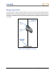
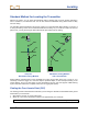
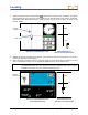
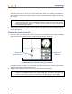
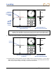
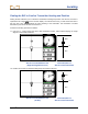
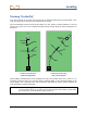
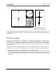
Table Of Contents
- Safety Precautions and Warnings
- Dear Customer:
- Introduction
- Receiver
- General Description
- Toggle and Trigger Switches
- Audible Tones
- Installing and Removing the Battery Pack
- Power On
- Power Off
- Main Menu
- Locate Mode
- Calibration Menu
- Height-Above-Ground (HAG) Menu
- Settings Menu
- Transmitter Selection Menu
- Drill DataLog Menu
- Pressure-Tension DataLog Menu
- Using the Keypad
- Display Screens
- Standard Receiver Display Screen Symbols
- Transmitter
- Remote Display
- Battery Charger
- System Setup
- Locating
- The Target Steering Function
- Appendix A: System Specifications and Maintenance Requirements
- Appendix B: Projected Depth Versus Actual Depth and the Fore/Aft Offset
- Appendix C: Calculating Depth Based on Distance Between FLP and RLP
- Appendix D: Reference Tables
- LIMITED WARRANTY

Locating
76 DigiTrak
®
F5™ Operator’s Manual
RLP
FLP
LL
Receiver Locate Mode Screen
(Approaching LL)
Actual Position of
Receiver and Transmitter
NOTE: Do not rely on the alignment of the ball with the vertical crosshair to identify the left/right
position of the transmitter. The front and rear locate points must be accurately found to
determine the transmitter’s lateral position (heading) and to take accurate depth readings.
9. Position the receiver so that the LL aligns with the horizontal crosshair.
RLP
FLP
LL
Receiver Locate Mode Screen
(at the LL)
Actual Position of
Receiver and Transmitter
10. Mark the location directly below the receiver’s display screen on the ground as the LL. You can take a
depth reading here by holding in the trigger. However, to be certain you are directly above the trans-
mitter, and your depth reading is accurate, you should first find the RLP.
Line-in-
the-box
Locate line
(red when not
aligned in box
for depth
reading)
Yaw
(left/right
rotation of
transmitter
relative to
receiver)