
User's Manual
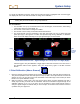
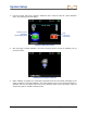
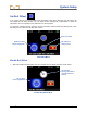
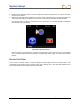
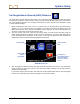


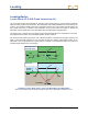
Table Of Contents
- Safety Precautions and Warnings
- Dear Customer:
- Introduction
- Receiver
- General Description
- Toggle and Trigger Switches
- Audible Tones
- Installing and Removing the Battery Pack
- Power On
- Power Off
- Main Menu
- Locate Mode
- Calibration Menu
- Height-Above-Ground (HAG) Menu
- Settings Menu
- Transmitter Selection Menu
- Drill DataLog Menu
- Pressure-Tension DataLog Menu
- Using the Keypad
- Display Screens
- Standard Receiver Display Screen Symbols
- Transmitter
- Remote Display
- Battery Charger
- System Setup
- Locating
- The Target Steering Function
- Appendix A: System Specifications and Maintenance Requirements
- Appendix B: Projected Depth Versus Actual Depth and the Fore/Aft Offset
- Appendix C: Calculating Depth Based on Distance Between FLP and RLP
- Appendix D: Reference Tables
- LIMITED WARRANTY

Locating
70 DigiTrak
®
F5™ Operator’s Manual
Locating Basics
Locate Points (FLP & RLP) and Locate Line (LL)
The F5 receiver locates the transmitter by detecting three specific places in the transmitter’s magnetic
field: the locate points and the locate line. The locate points are indistinguishable from one another by the
receiver. They represent similar points in the transmitter’s field in front of and behind the transmitter. The
front locate point (FLP) is ahead of the transmitter, and the rear locate point (RLP) is behind the
transmitter. (See Appendix B for more information about the transmitter’s magnetic field.)
The locate line (LL) extends 90° to the left and right of the transmitter when the transmitter is at 0% pitch,
and represents the location of the transmitter between the FLP and RLP.
The most accurate tracking requires the use of all three locations to determine the position, heading, and
depth of the transmitter. Aligning the FLP and RLP reveals the heading and left/right position of the
transmitter. The LL determines the central position and depth of the transmitter when the receiver is
properly aligned between the FLP and RLP.
LL
FLP
RLP
LL
FLP
RLP
70°
Geometry of FLP, RLP, and LL from Top (Bird’s-Eye) and Side Views
Note how the RLP and FLP are equal distances from the LL when the transmitter is level.
Bird’s-eye view
(looking down)
Side view
Transmitter
Transmitter
Drill
Axis line
Drill
Surface of
ground