
User's Manual
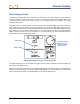
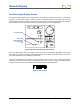
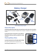
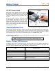

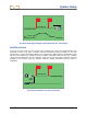
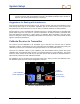
Table Of Contents
- Safety Precautions and Warnings
- Dear Customer:
- Introduction
- Receiver
- General Description
- Toggle and Trigger Switches
- Audible Tones
- Installing and Removing the Battery Pack
- Power On
- Power Off
- Main Menu
- Locate Mode
- Calibration Menu
- Height-Above-Ground (HAG) Menu
- Settings Menu
- Transmitter Selection Menu
- Drill DataLog Menu
- Pressure-Tension DataLog Menu
- Using the Keypad
- Display Screens
- Standard Receiver Display Screen Symbols
- Transmitter
- Remote Display
- Battery Charger
- System Setup
- Locating
- The Target Steering Function
- Appendix A: System Specifications and Maintenance Requirements
- Appendix B: Projected Depth Versus Actual Depth and the Fore/Aft Offset
- Appendix C: Calculating Depth Based on Distance Between FLP and RLP
- Appendix D: Reference Tables
- LIMITED WARRANTY

System Setup
60 DigiTrak
®
F5™ Operator’s Manual
NOTE: Electrical interference is determined by observing the signal strength with the transmitter
turned on and then with the transmitter turned off. If the difference between these numbers is
less than 150, the electrical interference is excessive.
Suggestions for Dealing with Interference
If the pitch/roll information becomes erratic or is lost, move the receiver away from the interference source
while staying within range of the transmitter. Separation (use of the HAG function) of the receiver from
both passive and active interference is known to reduce or eliminate interference-related problems.
Another option is to use a transmitter with a different frequency or greater depth range. A transmitter with
greater depth range has more power to overcome interference. A different frequency transmitter may
have less interference potential on a given jobsite. To determine which transmitter is the best option,
perform a background check using different transmitters and frequencies to see which provides the best
signal for overcoming interference.
Calibrate Receiver to Transmitter
The receiver must be calibrated to the transmitter prior to first-time use and each time a different
transmitter, receiver, or drill head is used. The transmitter must be installed in the drill housing during the
calibration procedure (see “Transmitter Housing Requirements” in the Transmitter section).
There are two calibration options: 1-point calibration (with the transmitter above ground) and 2-point
calibration (with the transmitter below ground). The preferred method is 1-point calibration. The 2-point
method is rarely needed and should only be used with caution. Both methods are described below. A
tape measure is required for both calibration methods.
The calibration menu is accessed from the receiver main menu. When you select the calibration menu,
the calibration option previously used is highlighted for selection.
Receiver Calibration Menu Screen
Exit (returns
to main menu)
1-point calibration
(shown highlighted)
2-point
calibration