
User's Manual
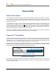
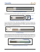
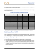
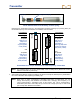
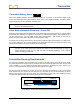
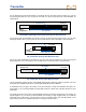
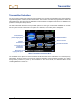
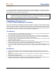
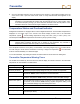
Table Of Contents
- Safety Precautions and Warnings
- Dear Customer:
- Introduction
- Receiver
- General Description
- Toggle and Trigger Switches
- Audible Tones
- Installing and Removing the Battery Pack
- Power On
- Power Off
- Main Menu
- Locate Mode
- Calibration Menu
- Height-Above-Ground (HAG) Menu
- Settings Menu
- Transmitter Selection Menu
- Drill DataLog Menu
- Pressure-Tension DataLog Menu
- Using the Keypad
- Display Screens
- Standard Receiver Display Screen Symbols
- Transmitter
- Remote Display
- Battery Charger
- System Setup
- Locating
- The Target Steering Function
- Appendix A: System Specifications and Maintenance Requirements
- Appendix B: Projected Depth Versus Actual Depth and the Fore/Aft Offset
- Appendix C: Calculating Depth Based on Distance Between FLP and RLP
- Appendix D: Reference Tables
- LIMITED WARRANTY

Transmitter
36 DigiTrak
®
F5™ Operator’s Manual
For the extended long-range transmitters (19 in./48.26 cm long), the slots must be at least 13 in. (33 cm)
long and begin at least 2 in. (5.1 cm) but not more than 3 in. (7.6 cm) from the front of the transmitter, as
shown below.
Extended Long-Range Transmitter Housing Slot Requirements
For the short-range FS transmitter (8 in./20.32 cm long), the slots must be at least 3.75 in. (9.5 cm) long
and begin at least 1.25 in. (3.2 cm) from the front or index cap end of the transmitter, as shown below.
FS Transmitter Housing Slot Requirements
For the FC cable transmitter (19 in./48.26 cm long), the slots must be at least 9 in. (22.9 cm) long and
begin at least 2.5 in. (6.4 cm) from the front or index cap end of the transmitter, as shown below.
FC Transmitter Housing Slot Requirements
The FC transmitter requires the use of the MFCB (multi-function cable box) system to operate. For more
information and complete instructions, see the DigiTrak MFCB Operator's Manual.
A transmitter must fit snugly in its housing. It may be necessary to wrap the transmitter with tape or O-
rings and/or to use a housing adapter for larger drill housings. Contact DCI Customer Service for more
information.
The index slot in the front end cap of the transmitter should fit onto the anti-roll pin (key) in the housing for
proper alignment. If you cannot get the transmitter and housing to align properly when you install the
transmitter in the drill housing, you will need to use the roll offset function. See “Set Roll Offset” in the
System Setup section for complete instructions on using the roll offset menu.
Slot position
2 in.
(5.1 cm)
Slot length
13 in. (33 cm)
Front end
Battery
compartment
Slot position
1.25 in.
(3.2 cm)
Slot length
3.75 in. (9.5 cm)
Front end
Battery
compartment
Slot position
2.5 in.
(6.4 cm)
Slot length
9 in. (22.9 cm)
Front end
Wireline end