
User's Manual
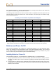
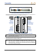
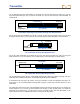
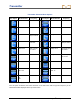
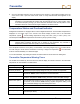
Table Of Contents
- Safety Precautions and Warnings
- Dear Customer:
- Introduction
- Receiver
- General Description
- Toggle and Trigger Switches
- Audible Tones
- Installing and Removing the Battery Pack
- Power On
- Power Off
- Main Menu
- Locate Mode
- Calibration Menu
- Height-Above-Ground (HAG) Menu
- Settings Menu
- Transmitter Selection Menu
- Drill DataLog Menu
- Pressure-Tension DataLog Menu
- Using the Keypad
- Display Screens
- Standard Receiver Display Screen Symbols
- Transmitter
- Remote Display
- Battery Charger
- System Setup
- Locating
- The Target Steering Function
- Appendix A: System Specifications and Maintenance Requirements
- Appendix B: Projected Depth Versus Actual Depth and the Fore/Aft Offset
- Appendix C: Calculating Depth Based on Distance Between FLP and RLP
- Appendix D: Reference Tables
- LIMITED WARRANTY

Transmitter
DigiTrak
®
F5™ Operator’s Manual 33
For complete instructions on using the DataLog system for recording pressure-tension data, please see
the DigiTrak LWD DataLog System Operator’s Manual.
The following table summarizes the various transmitters that are compatible with the F5 system. For each
transmitter model, it gives the model number, a brief description, the system type, the maximum range,
and the operating frequency.
Summary of Transmitters Compatible with F5 System
Model No. Description Type Maximum Range* Frequency
FS Short range F Series 15 ft (4.6 m) 12 kHz
FX Long range F Series 65 ft (19.8 m) 12 kHz
FX 19.2 Long range F Series 65 ft (19.8 m) 19.2 kHz
FXL Extended long range F Series 85 ft (25.9 m) 12 kHz
FXL 19.2 Extended long range F Series 85 ft (25.9 m) 19.2 kHz
5X 18.5 Long range F5 65 ft (19.8 m) 18.5 kHz
5X 8.4 Long range F5 65 ft (19.8 m) 8.4 kHz
5XD 19/12 Long range F5 65 ft (19.8 m) 19.2 or 12 kHz
5XD 12/1.3 Long range F5 65 ft (19.8 m) 12 or 1.3 kHz
FC Cable or wireline Cable 90 ft (27.4 m) 12 kHz
DDS 12 DucTrak – short range DucTrak 40 ft (12.2 m) 12 kHz
DDT 12 DucTrak – long range DucTrak 80 ft (24.4 m) 12 kHz
F5Dp 19/12 Fluid pressure monitor FPT 65 ft (19.8 m) 19.2 or 12 kHz
F5Dp 12/1.3 Fluid pressure monitor FPT 65 ft (19.8 m) 12 or 1.3 kHz
TT5 TensiTrak tension monitor TensiTrak 60 ft (18.3 m) 12 kHz
SST Short steering tool Cable 90 ft (27.4 m) 12 kHz
*The range of any transmitter is largely dependent upon the amount of interference at a job site. The
range decreases as interference increases. Transmitters in dual mode transmit up to 40 ft (12.2m).
Batteries and Power On/Off
The long-range transmitters each require two C-cell alkaline batteries or one DCI SuperCell lithium
battery. The extended long-range transmitters require one DCI SuperCell lithium battery. It is not practical
to use alkaline batteries in the extended long-range transmitters, because they would last only a few
hours. The short-range FS transmitter requires one AA alkaline battery.
Installing Batteries / Power On
The transmitter is powered on once the batteries are installed properly. To install the batteries:
1. Using a large flathead screw driver, remove the battery cap from the transmitter by rotating it counter-
clockwise. The battery cap on an FPT is removed by gripping the knurled cap and rotating it counter-
clockwise.
2. Insert the battery or batteries into the transmitter with the positive terminals first. When using two C-
cell batteries in the long-range transmitters, performance is improved by placing a spring between the
batteries, as shown below.