
User's Manual
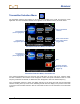
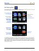
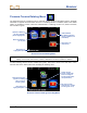
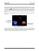
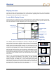
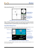
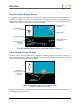
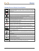
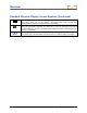
Table Of Contents
- Safety Precautions and Warnings
- Dear Customer:
- Introduction
- Receiver
- General Description
- Toggle and Trigger Switches
- Audible Tones
- Installing and Removing the Battery Pack
- Power On
- Power Off
- Main Menu
- Locate Mode
- Calibration Menu
- Height-Above-Ground (HAG) Menu
- Settings Menu
- Transmitter Selection Menu
- Drill DataLog Menu
- Pressure-Tension DataLog Menu
- Using the Keypad
- Display Screens
- Standard Receiver Display Screen Symbols
- Transmitter
- Remote Display
- Battery Charger
- System Setup
- Locating
- The Target Steering Function
- Appendix A: System Specifications and Maintenance Requirements
- Appendix B: Projected Depth Versus Actual Depth and the Fore/Aft Offset
- Appendix C: Calculating Depth Based on Distance Between FLP and RLP
- Appendix D: Reference Tables
- LIMITED WARRANTY

Receiver
DigiTrak
®
F5™ Operator’s Manual 29
Standard Receiver Display Screen Symbols
Transmitter Roll – Shows the transmitter’s roll position. A line points to the roll position,
and the roll value appears in the center of the clock. The number of roll positions is a
function of the transmitter (12 or 24). When roll offset is used, the letters “RO” appear at
the bottom left.
Warning Symbol – Appears when there has been a failure in the self-test.
Globe Icon – Identifies the regional designation number that appears on the receiver
startup screen; must match that on the transmitter battery compartment.
Roll/Pitch Update Meter – Shows the quality of data reception from the transmitter
(specifically, data rate). This feature lets you know if you are in an area of interference
or are reaching the range limit of the transmitter.
Transmitter Pitch Angle – The number next to this icon on the locate mode screen
indicates the transmitter pitch. It is also the menu selection icon for changing the pitch
angle units between percent and degrees.
Transmitter Signal Strength – The number next to this icon on the locate mode screen
indicates the transmitter signal strength.
or
Transmitter Temperature – The number next to either of these icons shows the
temperature of the transmitter (Fahrenheit when depth units are in feet or inches,
Celsius when depth units are in meters). An up or down arrow will accompany a change
in temperature. The icon on the right represents dangerous drilling temperatures.
Receiver Icon – Indicates the position of the receiver relative to the ground for the
height-above-ground (HAG) function, depth readings, the two-
point calibration
procedure, and the Target Steering function.
Ground Level – Represents the ground for the HAG function, depth readings, and the
two-point calibration procedure.
Locating Icon – Represents a bird’s-eye view of the receiver. The square at the top of
this icon is referred to as the “box” in the terms target-in-the-box and line-in-the-box
locating.
Locate Target – Represents the front and rear locate points (FLP and RLP). See the
Locating section.
Locate Line – Represents the locate line (LL). The LL is found at some location
between the front and rear locate points only after a reference point has been obtained.
See the Locating section.
R
Reference Lock – Indicates that a reference signal has been obtained for locating the
transmitter. See the Locating section.
Transmitter Battery/Drill Head – Depicts the remaining battery life of the transmitter
when alkaline batteries are used (full battery shown here). Also used to represent the
position of the drill head relative to the receiver in the depth screen.