
User's Manual
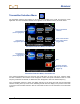
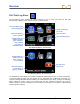
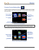
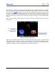
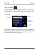
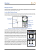
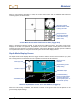
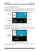
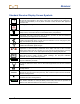
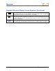
Table Of Contents
- Safety Precautions and Warnings
- Dear Customer:
- Introduction
- Receiver
- General Description
- Toggle and Trigger Switches
- Audible Tones
- Installing and Removing the Battery Pack
- Power On
- Power Off
- Main Menu
- Locate Mode
- Calibration Menu
- Height-Above-Ground (HAG) Menu
- Settings Menu
- Transmitter Selection Menu
- Drill DataLog Menu
- Pressure-Tension DataLog Menu
- Using the Keypad
- Display Screens
- Standard Receiver Display Screen Symbols
- Transmitter
- Remote Display
- Battery Charger
- System Setup
- Locating
- The Target Steering Function
- Appendix A: System Specifications and Maintenance Requirements
- Appendix B: Projected Depth Versus Actual Depth and the Fore/Aft Offset
- Appendix C: Calculating Depth Based on Distance Between FLP and RLP
- Appendix D: Reference Tables
- LIMITED WARRANTY

Receiver
26 DigiTrak
®
F5™ Operator’s Manual
Display Screens
The basic receiver screens include the locate mode screen, the depth mode screen, and the predicted
depth screen. These are presented below. For more information regarding these screens and for detailed
locating instructions, please see the Locating section.
Locate Mode Display Screen
The first option in the main menu is the locate mode option, which displays the locate mode screen.
When the receiver is detecting a signal from a transmitter, the locate mode screen provides real-time data
about the transmitter’s location, temperature, pitch, roll, and signal strength.
Receiver Locate Mode Screen with Transmitter in Range (Trigger Out)
The roll/pitch update meter displays the quantity of roll/pitch data being
received from the transmitter. When the meter is empty, no roll/pitch data is
being received, and none will appear on either the receiver or the remote
display. Depth and predicted depth readings may still be taken, but the
receiver will assume the transmitter has a pitch of zero, as indicated by the
image to the right appearing on the depth or predicted depth mode screen.
When the roll offset function is used (an electronic compensation to match
the transmitter’s 12 o’clock position to the drill head’s 12 o’clock position),
the roll indicator will appear as shown in the image to the right. For more
information on the roll offset function, see “Set Roll Offset” in the System
Setup section.
When a “12/1.3” dual-frequency transmitter (models 5XD 12/1.3 and F5Dp
12/1.3) in dual mode is detected by the receiver, the dual transmitter
symbol will appear to the upper left of the roll indicator as shown in the
image to the right. The letters “DL” or “DH” will accompany this symbol
when the receiver is set to detect the dual low (1.3 kHz) or dual high (12
kHz) frequency, respectively. For proper communication, the receiver must
be programmed to detect the dual mode transmitter. See “Transmitter
Selection” in the Transmitter section for more information.
Locating target
(FLP or RLP)
Transmitter signal
strength
Roll/pitch update
meter
Roll indicator
Transmitter
temperature
Transmitter pitch
Receiver
Pitch Assumed Zero
Roll Offset Activated
Dual Transmitter
Detected