
User's Manual
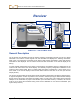
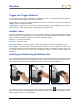
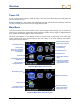
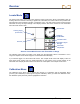
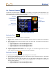
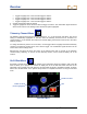
Table Of Contents
- Safety Precautions and Warnings
- Dear Customer:
- Introduction
- Receiver
- General Description
- Toggle and Trigger Switches
- Audible Tones
- Installing and Removing the Battery Pack
- Power On
- Power Off
- Main Menu
- Locate Mode
- Calibration Menu
- Height-Above-Ground (HAG) Menu
- Settings Menu
- Transmitter Selection Menu
- Drill DataLog Menu
- Pressure-Tension DataLog Menu
- Using the Keypad
- Display Screens
- Standard Receiver Display Screen Symbols
- Transmitter
- Remote Display
- Battery Charger
- System Setup
- Locating
- The Target Steering Function
- Appendix A: System Specifications and Maintenance Requirements
- Appendix B: Projected Depth Versus Actual Depth and the Fore/Aft Offset
- Appendix C: Calculating Depth Based on Distance Between FLP and RLP
- Appendix D: Reference Tables
- LIMITED WARRANTY

Receiver
12 DigiTrak
®
F5™ Operator’s Manual
Toggle and Trigger Switches
The F5 receiver has two types of switches for operating the system – a toggle (thumb switch) located on
the top of the unit and a trigger located under the handle.
Toggle Switch – Used to access and navigate menus. Moves in four directions: left, right, up (toward the
display), and down (toward the handle).
Trigger Switch – Used to turn on the receiver, to select menu options, and to change the screen view for
depth readings. Is either clicked or held in, depending on the desired action.
Audible Tones
The F5 receiver beeps to signal power on/off, to confirm menu changes, and to acknowledge the pass/fail
status of actions, as summarized below. The receiver also beeps with transmitter temperature increases
(see “Transmitter Temperature Warning Tones” in the Transmitter section).
Power On – A series of short beeps.
Power Off – Four short beeps.
Confirmation Signal – Four short beeps to confirm menu selection has been successfully executed.
Failure Signal – Two long beeps to indicate a problem with the menu option selected. A failure screen
will appear. The failure screen will display until the trigger is clicked or the battery is removed in the case
of a critical failure. Verify your setup and try the operation again or call DCI Customer Service for
assistance.
Installing and Removing the Battery Pack
Insert a fully charged DigiTrak F Series battery pack so that it is flush with the back of the receiver and the
tab is securely latched. To remove the battery pack, push down on the battery tab and pull it away from
the unit until the tab is released. Then lift the battery pack out of the battery compartment.
Inserting Battery Pack
Battery Pack Fully Inserted
Removing Battery Pack
To check the charge on the battery pack, push the battery status button located under the LEDs
below the battery tab. The LEDs will illuminate to indicate the amount of charge on the battery. See the
Battery Charger section for more information.
Battery
tab