
User's Manual


Transmitter
34 DigiTrak
®
F5™ Operator’s Manual
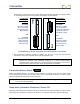
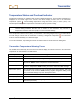
For the FC cable transmitter (19 in./48.26 cm long), the slots must be at least 9 in. (22.9 cm) long and
begin at least 2.5 in. (6.4 cm) from the front or index cap end of the transmitter, as shown below.
FC Transmitter Housing Slot Requirements
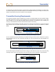
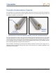
The transmitter must fit snugly in the housing. It may be necessary to wrap the transmitter with tape or O-
rings and/or use a housing adapter for larger drill housings. Contact DCI Customer Service for more
information.
The index slot in the front end cap of the transmitter should fit onto the anti-roll pin (key) in the housing for
proper alignment. If you cannot get the transmitter and housing to align properly when you install the
transmitter in the drill housing, you will need to use the roll offset function. See “Set Roll Offset” in the
System Setup section for complete instructions on using the roll offset menu.
Transmitter Selection
For the receiver to detect the signal from the transmitter, the receiver and transmitter must have matching
regional designation numbers, as discussed earlier. The receiver must also be programmed to detect the
transmitter being used and must be calibrated to that transmitter. Complete instructions for calibration are
provided in the System Setup section.
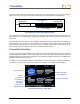
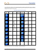
The main menu for transmitter selection is shown below. It shows each type of transmitter available for
use with the F5 system. If there is more than option for a selection, a secondary menu will appear.
Transmitter Selection - Main Menu
Slot Position
2.5 in.
(6.4 cm)
Slot Length
9 in. (22.9 cm)
Front End Ca
p
Wireline End
Description of
Highlighted Item
Cable Transmitte
r
Tension Monito
r
DucTrak Transmitte
r
F5 Transmitters
F Series
Transmitters
Fluid Pressure
Monitoring
Transmitters